I am fortunate enough to have a HiFi father that is a bit of a hoarder.
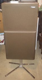
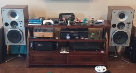
On a recent trip home for the 4th of July my father agreed to let me take ONE pair of his Technics SB-X50's home with me.
He purchased them new while he was on a trip to Japan in 1976.
They are rated at 93db sensitive and I would tend to agree with this rating based upon my initial low power tests.
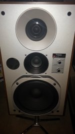
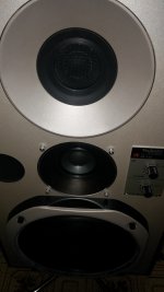
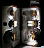
They have a 1" soft dome, 3.5" paper mid with inverted neoprene surround and a 10" paper woofer with inverted cloth surround.
The surrounds on all of the drivers are still in very good shape.
The rubber parts even still have that bit of white powder that new rubber has on it.
The factory crossover points are 1000hz and 3000hz.
As is they really sound very good even for being 40 years old with dried up electrolytic caps.
They image VERY well and I can hear things all around the room from directly in front and out to the sides even slightly above and below.
The drivers are physically time aligned and the speakers were marketed as Linear Phase design.
I will be going through them and replacing the old electrolytic capacitors with Met-Poly except for the 330uF in the midrange tank (that will be a mix).
They are in near pristine condition and have a very slight grunge in the sound which is the reason I will be replacing the capacitors in the crossovers.
In this thread I will chronicle my progress and field any questions along the way.
On a recent trip home for the 4th of July my father agreed to let me take ONE pair of his Technics SB-X50's home with me.
He purchased them new while he was on a trip to Japan in 1976.
They are rated at 93db sensitive and I would tend to agree with this rating based upon my initial low power tests.
They have a 1" soft dome, 3.5" paper mid with inverted neoprene surround and a 10" paper woofer with inverted cloth surround.
The surrounds on all of the drivers are still in very good shape.
The rubber parts even still have that bit of white powder that new rubber has on it.
The factory crossover points are 1000hz and 3000hz.
As is they really sound very good even for being 40 years old with dried up electrolytic caps.
They image VERY well and I can hear things all around the room from directly in front and out to the sides even slightly above and below.
The drivers are physically time aligned and the speakers were marketed as Linear Phase design.
I will be going through them and replacing the old electrolytic capacitors with Met-Poly except for the 330uF in the midrange tank (that will be a mix).
They are in near pristine condition and have a very slight grunge in the sound which is the reason I will be replacing the capacitors in the crossovers.
In this thread I will chronicle my progress and field any questions along the way.
Attachments
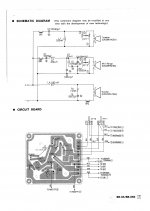
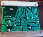
No Way, this crossover looks very well thought out even compared to the modern designs and ideas.
I bet the engineers at Panasonic had their thinking caps on when they designed these.
Somewhere my father has all of the original documentation including impulse and phase response graphs.
From some of the scans I have seen on the internet of this documentation there would be NO WAY I could even come close to designing something comparable myself.
I have however already thought about changing the vinyl walnut veneer for real walnut veneer.
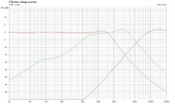
The crossover electric transfer would be similar to this, notice the inversion of phase on the tweeter (OP) working with horn loading.
In case someone wants to use other drivers, Visatons, SSs or others.
Technics SB-X50 on thevintageknob.org
In case someone wants to use other drivers, Visatons, SSs or others.
Technics SB-X50 on thevintageknob.org
Attachments
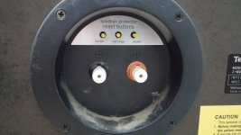
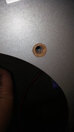
Well, Inductor pointed to the VKnob site, and it says. "Thermal relays for each drivers are placed at the input point of the speaker coils set in as soon as excessive heat builds up caused by amplifier clipping ; the reset buttons are located at the back, just above the terminals."
I would skip those !
I would skip those !
You must be shopping for the iron gates by now...I have children in the house so I think it would be wise to leave the driver protection in place for now.
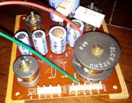
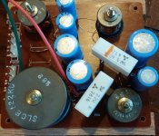
Crossover Shots
Hey Everybody,
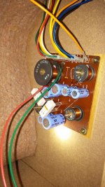
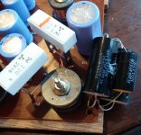
Here are some nice shots of the crossovers.
I tried winding an air core with 18awg for the .33mH (that measured .263mH).
It ended up being .31Ω DCR, the DCR of the factory P-Core is only .06Ω.
Will the .25Ω DCR make a noticeable difference?
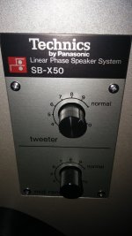
I have been running the Midrange 2db down from normal.
I think I should stick with the factory P-Core inductors, I doubt I will ever push enough watts into these to make them saturate.
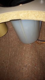
As you can see the midrange is chambered, COOL.
Also I was able to salvage my 6.8uF caps from my Silver AL's "UE" build to reuse in this project.
For some reason the schematic called for 3.3uF and there is a 6.8uF in both of the crossovers.
They must have had a redesign after the documentation was published.
Hey Everybody,
Here are some nice shots of the crossovers.
I tried winding an air core with 18awg for the .33mH (that measured .263mH).
It ended up being .31Ω DCR, the DCR of the factory P-Core is only .06Ω.
Will the .25Ω DCR make a noticeable difference?
I have been running the Midrange 2db down from normal.
I think I should stick with the factory P-Core inductors, I doubt I will ever push enough watts into these to make them saturate.
As you can see the midrange is chambered, COOL.
Also I was able to salvage my 6.8uF caps from my Silver AL's "UE" build to reuse in this project.
For some reason the schematic called for 3.3uF and there is a 6.8uF in both of the crossovers.
They must have had a redesign after the documentation was published.
Attachments
From the end ;
Cool that you have the right "replacements" for the caps
And from the beginning : I would try those new .25 R inductors together with
the suppression of the L-pad ( or simple variable resistor ) since you have
an added resistance - I would try for experiment even higher AWG -
You could really bybass - or better, redo with wire - all the pots and the breakers
And oh the crossover looks terrible - It's really a mess + It's inside the enclosure.
I've just described what if a so called purist would do to bring the speakers
singularly and all together la la la
Cool that you have the right "replacements" for the caps
And from the beginning : I would try those new .25 R inductors together with
the suppression of the L-pad ( or simple variable resistor ) since you have
an added resistance - I would try for experiment even higher AWG -
You could really bybass - or better, redo with wire - all the pots and the breakers
And oh the crossover looks terrible - It's really a mess + It's inside the enclosure.
What would you have expectedAs you can see the midrange is chambered, COOL.
I've just described what if a so called purist would do to bring the speakers
singularly and all together la la la
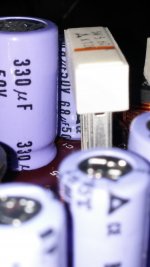
I'm not an expert on this but I think what you are seeing with the higher cap values can be explained. This is an artifact of converting polar capacitors to non polar capacitors. I did a quick google to support my foggy memory and found this link: Converting polar Electrolytic cap to NP - who is correct?
It sounds like it's an excellent idea to replace electrolytics where possible.
It sounds like it's an excellent idea to replace electrolytics where possible.
I have Silver PTFE wire coming from ApexJr with my order of capacitors.
I couldn't care less what "purists" have to say about the application.
I value their opinions but I'm not trying to break the bank here.
"Audiophool" 33uF caps are quite spendy and I don't really want to go that route.
The only inductor I am planning on changing is the .33mH in the midrange circuit.
The Erse Perfect Layer 14awg .27mH is rated at .09Ω and I will unwind them to .263mH to match the original since both inductors measured EXACTLY the same i figured it was on purpose.
The existing crossover capacitors are Panasonic Bi-Polar electrolytic so I shouldn't have to adjust values since all the rest match the stated values in the schematic.
- Status
- This old topic is closed. If you want to reopen this topic, contact a moderator using the "Report Post" button.
- Home
- Loudspeakers
- Multi-Way
- Rebuilding The Great Technics SB-X50