Bling,
Before trying randomly any crossovers and new tweeters I offer to design a custom crossover for your speaker based on manufacturer data. However, in order to do that, I need to know exact cabinet and port dimensions and the driver positions on the baffle. A picture usually helps very much and answers most of the questions.
Your own crossover design in post #13 basically is a correctly done theoretical crossover. Unfortunately, it doesn't factor in baffle step and actual driver impedance and frequency response. Thus it's of little practical benefit, but a good learning experience anyway.
Before trying randomly any crossovers and new tweeters I offer to design a custom crossover for your speaker based on manufacturer data. However, in order to do that, I need to know exact cabinet and port dimensions and the driver positions on the baffle. A picture usually helps very much and answers most of the questions.
Your own crossover design in post #13 basically is a correctly done theoretical crossover.
Unfortunately, it doesn't factor in baffle step and actual driver impedance and frequency response. Thus it's of little practical benefit, but a good learning experience anyway.Very kind of you Dissi
I realize were all here for learning and I did have a go with Boxim with not much luck so far.
I've seen somewhere it's mentioned the scanseak P21WO-20-08 is 88db and not 91 as stated on Madisound site. Just to confuse me even more!
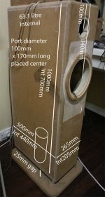
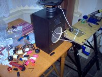
The bottom of the speaker is a cavity for filling with sand apparently. The port goes through the cavity to the bottom. Hence the difference between internal and external height.
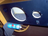
The box is very thick (30mm) and at present has next to no stuffing. Maybe you could advise me on this too?
I really appreciate your help.
I realize were all here for learning and I did have a go with Boxim with not much luck so far.
I've seen somewhere it's mentioned the scanseak P21WO-20-08 is 88db and not 91 as stated on Madisound site. Just to confuse me even more!
The bottom of the speaker is a cavity for filling with sand apparently. The port goes through the cavity to the bottom. Hence the difference between internal and external height.
The box is very thick (30mm) and at present has next to no stuffing. Maybe you could advise me on this too?
I really appreciate your help.
Attachments
The bottom of the speaker is a cavity for filling with
sand apparently. The box is very thick (30mm)...
Hey, looks like you are not worried about potentially hurting your back
.Wow, this cabinet probably will survive even a photon torpedo attack...
Everything clear about the dimensions. The woofer seems to be protruding by 1-2 cm, the builder obviously made an effort to align the acoustic centers of the drivers. That's very nice.
The tuning frequency of the port indeed is 40 Hz and gives a decent low frequency extensions. Unless you have complaints about the bass I would say that's fine.
Give me some time to come up with a crossover proposal.
Hi Andrew, I'm not sure that I follow.
Tony.
I would bet Andrew is searching for something that has not been written
in this fine community yet. A simple and accurate professional description
of how to make excellent sounding speakers. I am positive, this forum
will be enriched with it one day.
AllenB has done a good job writing "Introduction to ..." and if speakerdave
said it was good information, I guess it must be, considering everything.
...A simple and accurate professional description
of how to make excellent sounding speakers. I am positive, this forum
will be enriched with it one day.
AllenB has done a good job writing "Introduction to ..." and if speakerdave
said it was good information, I guess it must be, considering everything.
I think it IS possible to at least describe the issues that must be dealt with to build as good as possible 8" bass plus 1" tweeter!
An externally hosted image should be here but it was not working when we last tested it.
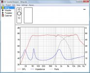
It's really cone breakup from the bass and the tweeter (resonance) Fs that must be filtered down. Below is a simple 1st order bass plus second order tweeter. All too often seen, but not atrocious.
An externally hosted image should be here but it was not working when we last tested it.
You also have fierce phase problems with this badly time aligned speaker. The KEF filters do quite a good job with that:
An externally hosted image should be here but it was not working when we last tested it.
Notice the characteristic energy storage above on an 8" cone at 3khZ, and 7kHz on both drivers, which is the S shaped kink in phase. This is going to sound bad or sibilant.
An externally hosted image should be here but it was not working when we last tested it.
Above is some quite steep rolloff to treat the problems. But we are mostly stuck with the 3kHz issues on the bass.
An externally hosted image should be here but it was not working when we last tested it.
What that filter does is notch the 7kHz bass breakup with the 0.33uF tank and the acoustic butterworth straightens out the tweeter response around the 2kHz FS. This is what you might call a detailed speaker.
I make no particular recommendation for the KEF circuit which has strengths and weaknesses IMO. For one thing you need a cast bass chassis to keep it sounding good, because shunt components increase damping from the voicecoil and push the chassis harder. The exact value of the bass shunt depends on woofer inductance, and you will usually add some resistance in practise.
Dissi is better at accurate sims than me, and we'll watch with interest what he comes up with!
Since we are a learning forum, I'd also recommend two particular designs that have relevance here. The TQWT- is a masterpiece for waveguide tweeter and 8" bass IMO.
But since you can never get rid of the 3kHz and dispersion issues on an 8" bass with a two way, the best speaker is going to be a three way: 3-Way Classic
That three way is just SO good. Troels Gravesen actually understands how to select a mid driver properly. It kicks most three ways into the dust. And I say that without even having heard it.
Well, here is the promised crossover proposal. Unfortunately I couldn't find any third party measurements of the drivers, so the design is based solely on manufacturer datasheets which contain 25 year old measurements. Very encouraging...
8" woofer and tweeter crossed higher than 1.5 kHz never can be done perfectly, because the woofer starts to beam above 1 kHz and frequency and phase response get more and more angle dependent. Nevertheless, many commercial speakers do it anyway and System7 regularly promotes this setup here in the forum too.
I came to the conclusion that two 2nd order filters basically should do the job. Crossover frequency is almost 3 kHz and the two caps you already have are reused. Adjust the tweeter level according to your taste by varying the 2.2 ohm resistor.
You will understand I can not garantee for success. If you decide to try the proposal it will be at your own risk. It's just a simulation and I only can hope and pray that the prediction will be halfway right.
Regarding damping of vented cabinets it's common practice to line only the walls with damping material. Volume and port always stay free.
Notes:
Microphone distance in the simulation is 3 m. A front port was choosen because a bottom port passing through a cavity was not supported by the software.
Attachments
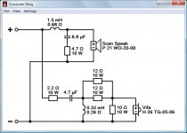
How important is the resistance of the Inductors. Is it a case of not having more resistance than what's in the schematic?
Component values are not really very critical. You often just go for the nearest preferred value. The theory on coils says that low DC resistance is always a good thing, or your reflex tuning calculation becomes inaccurate. But under an ohm DC resistance shouldn't cause a problem with a 6 ohm driver. Being a cheapish sort of person, I buy ferrites rather than exotic stuff for largish bass coils. They have low DC resistance anyway. My thinking is the woofer magnet is ferrite anyway, so what does it matter?
Looks a great crossover from Dissi there, as usual. It's really a TQWT- at heart.
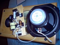
Crossover construction is a matter of taste, but wooden boards with tagstrip connectors have a lot going for them. Especially since metal PCBs seem to muck up coil inductance.
Soldering and desoldering should be fast and decisive to avoid cooking expensive components. Don't linger more than 5 seconds, especially where leads are short. Coils are made of enamelled wire, so you have to scrape the enamel off the ends for soldering. You can use 15-30A copper fusewire for any extra wiring. Tin your iron (40W at least with lead-free solder) the first time it warms up, and keep it tinned all the time it is hot to avoid oxidising the tip.
Panel damping is done with rubbery or bituminous stuff stuck on, and with a reflex you can do a tiny bit of cabinet damping with felt or similar on top of that. A carpet shop or home improvement store often has suitable materials. I usually fit a little rubber or card gasket to drivers to cut rattles out.
I think this is going to be about as good as it gets! Keep us updated.
Attachments
Last edited:
The Monoliths have awoken!
A huge improvement all -round.
The bass is actually working now!
Thanks for everyone’s help and thanks Dissi for your design. It seems to be spot on.
I’ll have to reverse engineer it now to see if I can work out the baffle step, notch filter and other goodies.
What’s the reason for the two 12ohm resistors in parallel?
I’ve also got some bits to make a shotgun microphone to do my own measurements in the future.
Cheers
Attachments
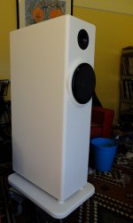
Very nice work, my friend.
You are pretty much state of the art with that speaker! Tidy crossover too.
TQWT-
The 6kHz RC notch that Troels employs on the bass is really quite optional. It is as easily replaced with a bigger rolloff capacitor as Dissi has done. An approach I prefer myself too.
You are pretty much state of the art with that speaker! Tidy crossover too.
TQWT-
The 6kHz RC notch that Troels employs on the bass is really quite optional. It is as easily replaced with a bigger rolloff capacitor as Dissi has done. An approach I prefer myself too.
That's good news from Australia. I'm relieved that the first impression is not too bad.
You really made a very nice finish on the cabinet and a beautiful crossover. Now take time to listen to the speakers carefully. It's like our diyAudio buddy ODougbo once said: Really good speakers are only those you still like after some weeks of listening.
If there should be an issue don't hesitate to address it. Perhaps some fine tuning helps.
The reason for the parallel resistors in the tweeter filter is power handling. Attenuating a tweeter by 10 dB means you burn 2/3 of the power in the series resistor.
In the meanwhile
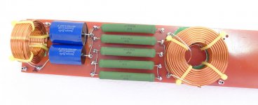
very nice work bling!
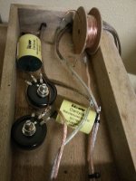
The only thing I would suggest is that the vertical mounted coil should probably be rotated 90deg on it's axis, but given the distance it is from the other coil and that they are already on different planes it's probably fine and just me being picky.
Rule of thumb is when looking through the centre of a coil you should not be able to see any other coil.
Tony.
The only thing I would suggest is that the vertical mounted coil should probably be rotated 90deg on it's axis, but given the distance it is from the other coil and that they are already on different planes it's probably fine and just me being picky
. Rule of thumb is when looking through the centre of a coil you should not be able to see any other coil.
Tony.
Thanks for advice. Unfortunately I haven't left enough room to turn it around.
The speakers are sounding really good so I leave it as is for now.
The finish worked out quite nice. I mixed a cup of Plaster of Paris with a litre of house paint and rolled it on with a spaghetti roller. After it dried I sanded off the peaks and gave it a normal coat. It ends up looking like stone.
Attachments
- Status
- This old topic is closed. If you want to reopen this topic, contact a moderator using the "Report Post" button.
- Home
- Loudspeakers
- Multi-Way
- 2 way crossover help