I am building a big-box 3-way and am getting close to putting it all together.
I have the drivers mounted, took acoustic and impedance measurements, figured out a crossover in PCD and ordered the parts.
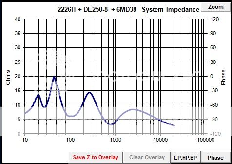
This is the first speaker I have built, so I'm not very experienced. It took me a while to tweak the crossover design to get something fairly flat, finally figuring I should put something together to get my bearings of where I actually am anyway, but one thing really bothers me about my crossover simulation currently, and that is the impedance curve. It has two places where it dips down to about 3 ohms. The speaker has all 8 ohm drivers.
My solid state amp won't have a problem with it, but I am really building this for an old tube amp, which can be stressed by a low impedance speaker.
At any rate, I am wondering if there are any general tricks to tweaking the impedance curve of a crossover design without adversely affecting the FR curve?
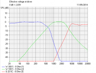
My design uses simple second order filters throughout, along with the necessary L-pads for the step response and to attenuate the horn tweeter. The Bass-mid crossover point is at 500 Hz. The first impedance dip is at 800 Hz, and seems to be coming from the mid crossover filters. The mid-tweet crossover point is about 1600 Hz, the lowest recommended for the horn. Unfortunately I did have to put a 5uF cap in series with the horn after the filter but across the L-pad to hold up a sagging top end, giving a falling impedance slope at the top of the response, which I assume only gets uglier as the frequency increases. The simulation ends at 3 ohms at 20K Hz.
All suggestions appreciated, even if not adopted.
I have the drivers mounted, took acoustic and impedance measurements, figured out a crossover in PCD and ordered the parts.
This is the first speaker I have built, so I'm not very experienced. It took me a while to tweak the crossover design to get something fairly flat, finally figuring I should put something together to get my bearings of where I actually am anyway, but one thing really bothers me about my crossover simulation currently, and that is the impedance curve. It has two places where it dips down to about 3 ohms. The speaker has all 8 ohm drivers.
My solid state amp won't have a problem with it, but I am really building this for an old tube amp, which can be stressed by a low impedance speaker.
At any rate, I am wondering if there are any general tricks to tweaking the impedance curve of a crossover design without adversely affecting the FR curve?
My design uses simple second order filters throughout, along with the necessary L-pads for the step response and to attenuate the horn tweeter. The Bass-mid crossover point is at 500 Hz. The first impedance dip is at 800 Hz, and seems to be coming from the mid crossover filters. The mid-tweet crossover point is about 1600 Hz, the lowest recommended for the horn. Unfortunately I did have to put a 5uF cap in series with the horn after the filter but across the L-pad to hold up a sagging top end, giving a falling impedance slope at the top of the response, which I assume only gets uglier as the frequency increases. The simulation ends at 3 ohms at 20K Hz.
All suggestions appreciated, even if not adopted.
Hi,
http://audio.claub.net/Simple Loudspeaker Design ver2.pdf
FRD Consortium tools guide
http://web.archive.org/web/20090902124715/http://geocities.com/woove99/Spkrbldg/DesigningXO.htm
You need acoustic targets for your x/o points, 2nd order L/R
bass to mid and 4th order L/R mid to treble is a sensible option.
All 8 ohm drivers should never dip to 3 ohm in any circumstances
I don't understand your treble EQ which sounds completely wrong.
Your x/o points seem too close together for a sensible design.
rgds, sreten.
Last edited:
Sreten,
Thank you for your reply. That sounds like it's all very good advice. I had not seen the Simple Loudspeaker Design PDF before. Scanning through it, I can see I will enjoy studying it. The FRD Consortium page I had seen before, though it looks different from how I remember it some years ago. The third link, I'm afraid, is now defunct.
The thing is that most of what these resources seem to go over is the rudiments of driver simulation, and cabinet and crossover design. As my OP says, I have already done 99% of that. I have a cabinet, I have drivers, I already have a crossover that gives close to the output I want. Of course, as I also stipulated, I am a newby at this. The thing is I have read a LOT on various sites and in books about this subject, but the bottom line is that I'm not an acoustic engineer. I'm a hobbyist, a hobbyist with a full time job that is not acoustical engineering and whose primary hobby, in between regular home maintenance and family duties, is antique electronics - I have a nice little collection of Fisher and Bogen tube gear. What I do not have and can't afford is a decent speaker, so I have marshaled my meager resources towards that end, and as I have said I have read a lot and done quite a bit of work to get this far.
The trouble seems to be that though I have read a lot I can't say that I have completely understood everything that I have read. So, I came here, hoping for less of a generic set of links and perhaps more of a little guidance.
So, I am hoping you will explain a little more of your advice about 'acoustic targets' and the crossover topology you recommended. I am most interested in seeing some discussion about this.
Thanks again.
Try raising the crossover frequency between the mid driver and the tweeter (Fh) to 4 kHz, that is, 3 Octaves above 500 Hz or the crossover frequency between the bass driver and mid driver(Fl).
Here is what Vance Dickason says in his Cookbook, and I quote,
"Generally speaking, the further apart the two crosspoints are, the better the combined response of the drivers will be (three octaves is a good starting point). Crosspoints closer together than the three octaves ideal will suffer from complicated undesirable interference patterns."
Not too long ago I put together a 4 way system with Fl = 500 Hz and Fh = 200 Hz (2 Octaves apart). Initially I tried all of the filters 2nd Order LR. It sounded horrible. Then I tried all of the filters 1st Order, except 2nd Order high-pass to the tweeter (to protect it from damaging low frequency signals) and the sound was perfect. Unfortunately I didn't switch based on measurements, but just the difference of sound quality was enough to convince me to use the second crossover.
Regards,
cT
Eric, you have made a lot of work for yourself so late in the day. 
You're right that 3 ways tend to have low impedance because of the middle driver. Impedance falls low right at the centre of the peak in the mids response.
The tweeter filter should be amenable to a bit of redesign, but I suspect your problems are because the bass is too efficient, and the mid and treble have to be driven hard to keep up. You traditionally raise impedance by putting resistance in front of the filters, rather than after.
But the fact is, that 3 ways are hard, especially on phase, and some drivers don't play nicely together. Here's a 12", 4" and 1" dome, a classic combination that DOES work.
Naturally, you might get more help here if you listed the drivers, box and posted the schematic. Is it all "Hush, Hush"?
Attachments
Yes post up the crossover schematic and the simulated impedance plot. That will give us more to go on.
One of the things that I have come accross in modeling that causes a big dip in impedance can be the use of too large a cap in a shunt position. This would be on your low pass filter for the bass unit or the LP section of the mid filter for the midrange.
This will be especially problematic if the coil is too small. (it might be summing flat but the coil isn't doing enough and the cap is doing too much).
edit: although I haven't encountered it, the same could go for HP sections I guess, if too large a cap is used with a small coil in shunt...
Tony.
Last edited:
Such great responses! Where to start?
The drivers are JBL2226H, B&C 6MD38, and B&C DE250-8 with Denovo SEOS-12 horn. The box is a bit of a monstrosity, a 'Test Cabinet' I made with testing different drivers in mind. It's vented, 48.5" tall, 25.5" wide, and 14.5" deep. Internal volume is about 7 1/2 CF. Yes, I know that's rather shallow, but my space is very limited, So I designed it to go fairly flat against a wall. I have actually re-stuffed it 9 times to eliminate reflections and resonances, and have been pretty successful. The bass is flush mounted, and the mid and tweet are mounted on a removable baffle, allowing me to try different configurations. I have redesigned the mid enclosure twice, and changed from a Selenium D220Ti with a HC23-25 horn to the present configuration. The speaker is very heavy, well braced, and mounted on castors with handles on the side so I can lug it outside for measurements. After I am done with my experiments I hope to continue to use the speaker in my shop, moving on to other projects.
The point about the proximity of the crossover points is well made, however Vance Dickason also talks a great deal about 'beaming' and power response. In his section on 'Driver bandwidth and crossover frequency' on page 186 (7th edition) he points out clearly the recommended 'Horizontal polar response criteria' in table 7.4. He doesn't list a 6 inch driver, but interpolating between the 7 and 5 inch drivers I think I fell right in the ball park. On the low end, I actually went overboard to give the mid a bit more to do. As such, the mid really is just a filler between the bass and the tweet - but isn't that it's function anyway?
I do have an L-pad on the mid, but unfortunately PCD 7 does not allow you to sim putting it in front of the filter, though that sounds like just the kind of idea I was looking for. I will try it out when I get the parts.
I will have to draw out the schematics in visio and save it as a JPG or some such to post it, and convert the graphs to JPG too. I will do it as soon as I am able.
Last edited:
It has two places where it dips down to about 3 ohms. The speaker has all 8 ohm drivers.
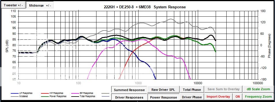
Post your circuit and your PCD screen which shows component responses and sum. Dips can be due to any number of things.
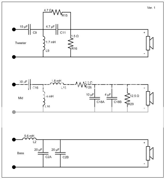
You do not haveto use an L-pad to attenuate a driver. In PCD, try using just a series resistor (ie. ditch the parallel resistor), either before the xo, after it, or both. Each option may change the shape of the response somewhat so the xo may need to be tweeked but the impedance will definitely be increased.
See Dickason, page175, "7.60 Driver Attenuation Circuits".
See Dickason, page175, "7.60 Driver Attenuation Circuits".
Eric,
I have experience with the B&C 6MD38. Its sensitivity is actually much lower than rated. More like 93-94 db/2.83V. It didn't pair well with my Selenium 18SWS800's at around 96 db/2.83v. It may be a little low for your JBL as well.
I ended up using the B&C 6PEV13, with about 98 db/2.83V sensitivity. It sounds great with just a touch of attenuation. Cross it over at 400 or above and its xmax will not be an issue even at very loud levels. BTW - I am using the DE250 tweeter as well - a good choice.
Karl
I dont't see anything along the lines of what I posted before....
Could you post the fr graph with phase as well? Also individual woofer, mid, tweeter with target responses too. It might just be the pcd display, bit to me it looks like there is a lot of overlap at the cross points ( and I'm surprised it sums as flat as it does).
Could you post the fr with the mid reversed as well?
The falling impedance from 3k is odd... are you sure your zma for the tweeter is ok?
Tony.
Yes but that is what you want if you have measurements taken on the baffle
If you don't then using Jeff Bagbies spreadsheet (I can't remember which one) allows you to adjust the driver curves to include the effects of baffle step.
In other words it is a tool that will give the best results if you have measurements of your drivers taken, mounted in the actual final boxes. That doesn't mean it can't be used to simulate what you could expect in a theoretical design with the aid of some other software.
Tony.
Last edited:
- Status
- This old topic is closed. If you want to reopen this topic, contact a moderator using the "Report Post" button.
- Home
- Loudspeakers
- Multi-Way
- Optimizing Impedance Curve