There are no formulas that i know of.
Coolio.
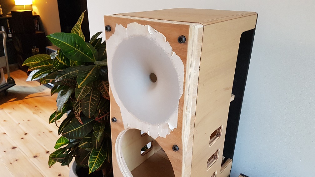
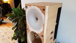
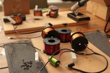
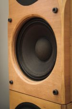
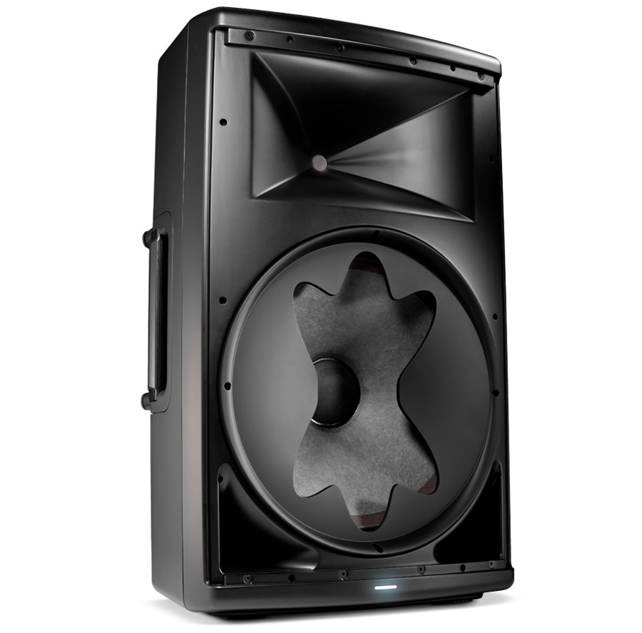
'The material that is used for the inside is Akortherm. The woofer is the AD R1030, from some less known chinese manufacturer.
Ah ok thanks. What made you change to this material?
Save
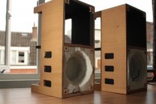
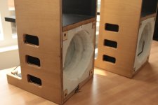
Still work in progress, but final version is coming up
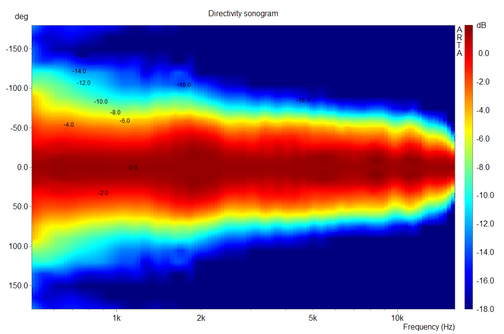
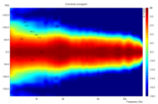
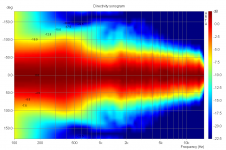
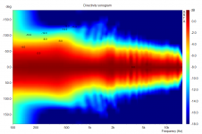
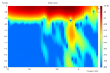
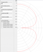
Directivity sonogram of woofer approximates cardioid to hypercardioid

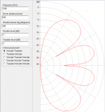
Waveguide directivity sonogram shows constant directivity from xover (1KHz) to 10KHz with some narrowing in top octave.
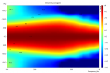
Directivity sonogram of woofer approximates cardioid to hypercardioid
Waveguide directivity sonogram shows constant directivity from xover (1KHz) to 10KHz with some narrowing in top octave.
Attachments

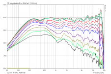
And we're progressing. I've built a first version of a passive filter. Its a 3rd order electrical 4th order acoustical low pass filter and 4 notches for the HF part. I also did some extra work on the cabinets finish. And measured the full range directivity.
The directivity approximates a full range cardioid pattern and is an improvement over the previous version. However, there is some room for improvement. Around 400Hz it becomes somewhat wider, which might improve by changing the damping material. And between 1 and 2 KHz the polar narrows somewhat, i think because of the woofer narrowing. I'm going to try to lower the xover frequency to 900Hz and re-do the polar and add some distortion measurements.
The directivity approximates a full range cardioid pattern and is an improvement over the previous version. However, there is some room for improvement. Around 400Hz it becomes somewhat wider, which might improve by changing the damping material. And between 1 and 2 KHz the polar narrows somewhat, i think because of the woofer narrowing. I'm going to try to lower the xover frequency to 900Hz and re-do the polar and add some distortion measurements.
Attachments
-
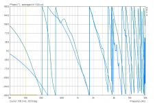 v1.0 woofer+tweeter phase.png16.5 KB · Views: 291
 -
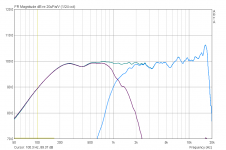 v1.0 woofer+tweeter amplitude.png38.4 KB · Views: 359
 -
 v1.0 sonogram.png128.6 KB · Views: 443
 -
 v1.0 overlays.png64.8 KB · Views: 505
 -
 10.jpg333.9 KB · Views: 546
 -
 9.jpg315.1 KB · Views: 523
 -
 6.jpg516.2 KB · Views: 447
 -
 5.jpg336.9 KB · Views: 488
 -
 3.jpg330.1 KB · Views: 451
 -
 1.jpg367.9 KB · Views: 336
Approaching the finish of this project. I tried a 900Hz xover, which resulted in a marginally better polar response. However, at the expense of more distortion. So i have decided to use the 1.2 KHz xover.
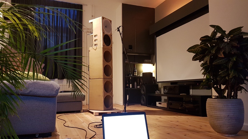
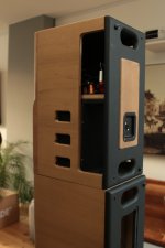
I finished the cabinets, and installed them in my living room. I don't care much for long descriptions of how speakers sound, but in short I'm quite pleased with the sound so far. There seems to be a tiny bit of harshness in the upper octave, so it might help to reduce the 16KHz peak.
Im going to re-run the multi sub optimizer software to optimize integration withs my 4 subs. However, sub and low frequency reproduction is already quite good. It's a very pleasant system to listen to. And im still missing one capicitor on one of the filters (resulting in a midrange dip), so that should result in some further improvement.
I finished the cabinets, and installed them in my living room. I don't care much for long descriptions of how speakers sound, but in short I'm quite pleased with the sound so far
. There seems to be a tiny bit of harshness in the upper octave, so it might help to reduce the 16KHz peak.Im going to re-run the multi sub optimizer software to optimize integration withs my 4 subs. However, sub and low frequency reproduction is already quite good. It's a very pleasant system to listen to. And im still missing one capicitor on one of the filters (resulting in a midrange dip), so that should result in some further improvement.
Attachments
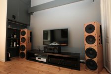
They look really nice now they are finished, you had to squeeze them into that room
How does the cardioid and waveguide work with your room in that position as it is so close to the walls.
I wouldn't mind a much bigger room, that's for sure. Still, one of the advantages of cardioid midbass is that the null at the back of the speaker is directed at the front wall (behind speaker), so it shouldn't be of much influence. The midbass sounds very clean. The back wall is dampened by a 200x100cm panel with 80mm high denisity rockwool. The acoustics of the room are quite pleasant (wooden floor with space underneath).
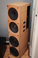
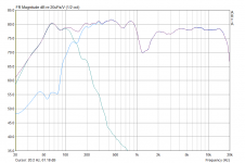
For the sub, im using four dual 10inch sealed subs, optimized by multi sub optimizer. I will redo the optimization the coming weeks. I'm using a 4th order low pass on the front subs and 2nd order high pass on the tops. Which results in a 5th order acoustical roll off for both and good match in phase @ 150Hz. Attached is a measurement to confirm the summation of sub and top. Measurement was performed indoors in the farfield (without linkwitz transform on the sub) and without gate. It also shows a dip because of floor bounce.
Attachments
very very cool! Nice balance between CD speaker and (at least somewhat) WAF speakers. This set is I think on the high-end of DIY effective good audio: Good response, low distortion, almost perfect power response, very, very good sub and all in all very well integrated.
I live close by Jag and have heard the system. It is great!
I live close by Jag and have heard the system. It is great!
Hi, I am very impressed by your results.
I am planning a cardioid enclosure for the new Seas C18EN002 coax chassis and would like to ask if you can give recommendations concerning the depth of the U frame and the placement and cut out area of the side vents?
Do you think other damping material like Basotect, Fibsorb will work as well?
Thanks,
Stephan
Hi, I am very impressed by your results.
I am planning a cardioid enclosure for the new Seas C18EN002 coax chassis and would like to ask if you can give recommendations concerning the depth of the U frame and the placement and cut out area of the side vents?
Do you think other damping material like Basotect, Fibsorb will work as well?
Thanks,
Stephan
Rule of thumb for cut out area is at least 1/2 * Sd.
My previous design had a depth of 22cm, which resulted in resonance in the u frame which affected the polar. My current design uses a depth of 10cm to the vents, which improved the directivity (more constant).
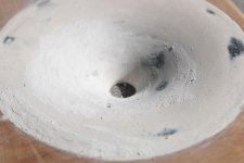
I have used rockwool before, which works fine. However, i prefer akotherm because is more firm and has less tendency to change shape / move.
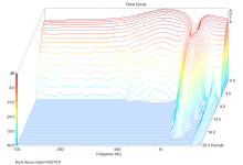
Currently, I'm thinking about replacing the midwoofer. Find colouration in de 500-1000 Hz Octave is bothering me. It also shows up at multiple frequencies in the burst decay plot. After some testing, it appears to be related to the ,a&d r1030 midwoofer. Currently, I'm thinking about the B&C 10ps26 as replacement. Do you have other suggestions? Frequency range is 120 - 1200hz.
I ended up with the Beyma 10g400 as replacement midbass driver. It's better, but i'm still not satisfied with the midrange. The lowend sound of my system is phenomenal, as is the imaging. However, the midrange still sounds coloured and i need extra EQ to make it sound acceptable.
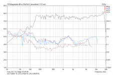
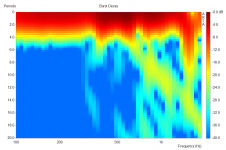
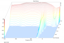
The attached burst decay shows a near field measurement of the Beyma 10g400, which i think shows the problem. It's just somewhat better than the previous midbass driver, the A&D r1030, the second image. Maybe the whole idea of a 2 way using a 10inch midbass and waveguide combo is not possible without coloured midrange??
Im now considering to try a 10inch HiFi midbass. There are not much of those, the best i can think of is the Dayton RS270 but there are people advising against using it above 400Hz. It has a paper version as well, which shows irregularities in the impedance plot in the passband (intened pass band is 120 - 1200Hz). It is marketed as midbass driver though, unlike the alu version. The alu version has a clean impedance plot apart from a strong 1400Hz resonance, which is just out of the passband and could be further reduced by a notch (crossover will be dsp). Directivity looks good for both drivers.
Do you have better suggestions for a 10inch HiFi driver for 120 - 1200Hz applicationd and minimum xmax 5mm? And any suggestions on the paper - alu versions of the RS270?
Attachments
The main reason for a 10" cardioid midrange sounding bad might be it's transition to "normal" monopole radiation pattern at around 1-2kHz. There is a majestetic change that nearfield measurements don't show! Measure at at least 1m distance in the baffle, use 6-9ms gating and no smoothing! Measure also off-axis up to at least 60¤ preferably up to 180¤ horizontally.
What kind of baflle are you using? Baffle dimensions contribute to that transition too, in a wide baffle transition is even lower in Fq, might be around 500Hz.
Please study this! http://www.diyaudio.com/forums/multi-way/192737-2-waveguide-cardioid.html#post2641262
What kind of baflle are you using? Baffle dimensions contribute to that transition too, in a wide baffle transition is even lower in Fq, might be around 500Hz.
Please study this! http://www.diyaudio.com/forums/multi-way/192737-2-waveguide-cardioid.html#post2641262
The main reason for a 10" cardioid midrange sounding bad might be it's transition to "normal" monopole radiation pattern at around 1-2kHz. There is a majestetic change that nearfield measurements don't show! Measure at at least 1m distance in the baffle, use 6-9ms gating and no smoothing! Measure also off-axis up to at least 60¤ preferably up to 180¤ horizontally.
What kind of baflle are you using? Baffle dimensions contribute to that transition too, in a wide baffle transition is even lower in Fq, might be around 500Hz.
Please study this! http://www.diyaudio.com/forums/multi-way/192737-2-waveguide-cardioid.html#post2641262
Thank you for the reply
See this post for a 360degree polar of the woofer (which is also available for the waveguide and a full range of woofer+wavegeuide). Those measurements were performed at a distance of 1m. The woofer directivity appears to match the direcivity of the waveguide quite well at the xover frequency.
I "hear" the problems in the 600 - 900Hz range, this is also where you see energy storage in the burst decay. Im not very experienced with interpreting the info of a burst decay. My guess would be that it's caused by cone breakup. The drivers i've used uptill now are both paper cones, which probably have better damped cone breakup modes that are lower in frequency (and therefore in the passband).
I've just ordered the Dyaton rs270-8. It might be a bit out the ordinary to use this woofer up that high, but i would expect the cone break up to be just outside the passband. I'll do a burst decay measurement, ill return them if it's really bad.
Open back cone drivers give strange noises, I suspect mostly cone-spider interference and coil vents. At "dipole axial nulling" frequency, radiation is 360 and it "rings like a bell".
Usually one can hear them easily in long sine sweeps. Play the problematic reguency sine and listen to it!
Usually one can hear them easily in long sine sweeps. Play the problematic reguency sine and listen to it!
Impressive project!And we're progressing. I've built a first version of a passive filter. Its a 3rd order electrical 4th order acoustical low pass filter and 4 notches for the HF part. I also did some extra work on the cabinets finish. And measured the full range directivity.
The directivity approximates a full range cardioid pattern and is an improvement over the previous version. However, there is some room for improvement. Around 400Hz it becomes somewhat wider, which might improve by changing the damping material. And between 1 and 2 KHz the polar narrows somewhat, i think because of the woofer narrowing. I'm going to try to lower the xover frequency to 900Hz and re-do the polar and add some distortion measurements.
Just a suggestion: To reduce the narrowing of the polars between 1 and 2 kHz you could cover up parts of the woofers sides:
Easy to do as you are rear mounting.
/Anton
I haven't tried it yet. What do you mean by the dipole axial nulling frequency?Open back cone drivers give strange noises, I suspect mostly cone-spider interference and coil vents. At "dipole axial nulling" frequency, radiation is 360 and it "rings like a bell".
Usually one can hear them easily in long sine sweeps. Play the problematic reguency sine and listen to it!
Impressive project!
Just a suggestion: To reduce the narrowing of the polars between 1 and 2 kHz you could cover up parts of the woofers sides:
Easy to do as you are rear mounting.
/Anton
Thats a good suggestion. However crossover is @ 1,2KHz currently, so it would be mostly related to the waveguide / baffle combo i would guess.
I also just received the Dayton RS270-8 reference (alu version). The third candidate midwoofer
. I did an outdoor measurement for the burst decay, and it looks as expected: a resonance @ 1,25KHz and its looks clean below. The burst decay is attached, as is the burst decay of the A&D R1030 for comparrison. I have to adjust the baffle somewhat for this Dayton woofer to fit. It will need at least a 4th order filter and a notch i would think. And maybe even a higer order filter at a lower frequency. I will try multiple versions for the crossover (i can switch easily with the miniDSP c-dsp). Now let's wait and hear if it will also result in a sound quality improvement .Attachments
Sure, my suggestion will mainly affect off-axis response of the woofer above maybe 500 Hz. But look at the trend when following off-axis measurements from 500 Hz upwards in frequency. That downward slope should be possible to remove, causing a more even handover to the tweeter.Thats a good suggestion. However crossover is @ 1,2KHz currently, so it would be mostly related to the waveguide / baffle combo i would guess.
Now the woofer is narrowing (beaming) at XO, maybe better if it didn't.
/Anton
As you know, 2 sources with opposite phase provide a clean dipole pattern across a limited frequency range. The pattern splits & rotates at higher frequencies. A 500mm baffle makes a beautiful dipole pattern at 345Hz. Put 1380Hz (4x) thru it, and...I haven't tried it yet. What do you mean by the dipole axial nulling frequency?
But, @Juhazi, how do you have a 360 pattern when there's an axial null???
Attachments
- Status
- This old topic is closed. If you want to reopen this topic, contact a moderator using the "Report Post" button.
- Home
- Loudspeakers
- Multi-Way
- Full range cardioid