Ryan,Hey Art-
I'm not sure I'm following completely, are you saying there is a reason why a 22" margin of error is the minimum for a speaker in a 11" wide box?
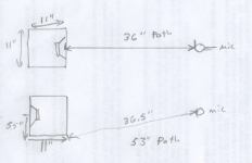
My mistake, the minimum path length difference on a 11" square box measured at 36" would be 17", not 22", a minimum path length difference of 53" at 180 degree compared to the 36" on axis measurement.
Art
Attachments
That makes sense-
So the overall directivity there is exaggerated by ~3.5dB...But if it is actually only ~8-12dB of front to back discrimination that's still pretty good no? You can certainly here a substantial drop walking around it with sines or pink noise.
I'll do some more with just the cab when I get a chance, I'll try 10ft? I'm in the city so it's not that quiet around here. That should leave only a ~1dB margin of error, and do some with mdf clamped over the box. It might be a while though because they are working out pretty nicely.
I do think the box needs more holes, at high spls there can still be some chuffing noises, especially with sines or certain bass sounds. Mostly at excessive levels, but it's still something I want to address in the next iteration.
RyanC, perhaps you can do some test sweeps? I have "standardized" my measurement so that rotating center is at the front baffle plane. With that setting I get some directivity too low. The acoustic center of a transducer is actually in front of it but it also depends on frequency. Please try also rotating at 5cm (2") in front of baffle if you can! Then look for differencies.
Ryan,So the overall directivity there is exaggerated by ~3.5dB...But if it is actually only ~8-12dB of front to back discrimination that's still pretty good no? You can certainly here a substantial drop walking around it with sines or pink noise.
An 11" baffle will limit dispersion of frequencies above it's wavelength (about 1233 Hz) to 180 degrees, so in addition to the 3.5 dB rearward loss of all frequencies due to inverse distance loss, half the audio spectrum is attenuated rearward simply by the baffle. You can certainly hear a substantial drop walking around any front loaded box with pink noise or program material, to make a determination of what impact your porting scheme is imparting on the polar response, an A/B test with the same box with the ports located on the front panel would be required.
A ten foot mic distance would eliminate most of the inverse distance problem from your tests, and also put the mic more effectively in the far field, where the acoustic center of the cabinet will have less effect on the measurements.
Art
Running polars from a greater distance will certainly help accuracy, but I don't think the whole 3.5 dB error applies here. RyanC is trying to make the classic first order gradient, similar to what Olson described years ago. Usually they are modeled as 2 elements 1/2 wavelength apart and equal strength but opposite phase. Since they are equal strength then the polar error (of one element swinging around well off the axis of rotation) doesn't seem to apply.
The directivity achieved looks like a useful amount and the LF response is still quite respectable.
I like it.
David S.
The directivity achieved looks like a useful amount and the LF response is still quite respectable.
I like it.
David S.
That should be 1/4 wave of physical spacing and about 1/4 wave of "electrical" delay. The electrical delay comes from the resistive venting and cabinet depth. In the forward direction the 1/4 + 1/4 delay is half wave of shift which just balances the out of phase nature of the rear contribution. However, looking in the opposite direction the two 1/4 wave delays cancel out and the out of phase aspect gives strong cancelation in the rearward direction.
Cardioid microphones use exactly the same principle.
David S.
Cardioid microphones use exactly the same principle.
David S.
1/4 wave of which frequency? This kind of setup has lots of amplitude response wobbling above certain Fs.
This is a single driver dipole (theoretical)

A cardioid study with U-frame by John K
DIY-dipole-1
Some studies and speakers with cardioid bass and midrange here http://kimmosaunisto.net/
This is a single driver dipole (theoretical)
A cardioid study with U-frame by John K
DIY-dipole-1
Some studies and speakers with cardioid bass and midrange here http://kimmosaunisto.net/
Last edited:
Ryan,
An 11" baffle will limit dispersion of frequencies above it's wavelength (about 1233 Hz) to 180 degrees, so in addition to the 3.5 dB rearward loss of all frequencies due to inverse distance loss, half the audio spectrum is attenuated rearward simply by the baffle. You can certainly hear a substantial drop walking around any front loaded box with pink noise or program material, to make a determination of what impact your porting scheme is imparting on the polar response, an A/B test with the same box with the ports located on the front panel would be required.
A ten foot mic distance would eliminate most of the inverse distance problem from your tests, and also put the mic more effectively in the far field, where the acoustic center of the cabinet will have less effect on the measurements.
Art
Right of-course, the crossover frequency to the seos 24 is 450hz though in the 180s there.
the polar error (of one element swinging around well off the axis of rotation) doesn't seem to apply.
I was thinking something along those lines myself, but am unsure. In any case, on of the things that initially had scared me off of this is it seems so fidgety, with nothing like hornrsp to model it completely.
But in practice, it seems to be more forgiving than that.
1/4 wave of which frequency? This kind of setup has lots of amplitude response wobbling above certain Fs.
This is a single driver dipole (theoretical)
A cardioid study with U-frame by John K
DIY-dipole-1
Some studies and speakers with cardioid bass and midrange here DIY Loudspeakers Kimmo Saunisto
I think the idea is to work primarily in the region below the first maxima. Most of the designs (this included) have a bandpass of rear output (essentially a damped port) that will give useful directivity in the first Octave or so. Above that the driver directivity will blend in giving a pretty seamless transition.
This is also one good application of TL designs.
David S.
+ high enough GFR on the rear vent is a acoustic LPF, it only takes 6dB to be effectively out of the way WRT the front wave interacting with the vented rear one. IMO this is the next big *thing*. I've been listening to the cheapo dayton drivers in this setup and aside from the vent sd not being enough this is IT.
Please correct me if I'm wrong, but is there a better horizontal polar out there?
This can be perfected further though....and I'm on it. I think a smaller diaphragm will mate even better with the SEOS, I'm going to try they aura ns6's next (have them) and some larger woofers also loaded card next...
- Status
- This old topic is closed. If you want to reopen this topic, contact a moderator using the "Report Post" button.
- Home
- Loudspeakers
- Multi-Way
- Promising loaded cardioid woofer test