#System7
Haha xD
Sorry..
I'm not just going to buy new tweeters and plug them into the speakers as they are. I'm listening to every word you guys are saying")
I'm gonna pay my friend a wisit again, to build a new crossover with these tweeters which i won't buy before I'we heard them(he has them), and I will try to present your ideas for him and se what he says
I will then save the old tweeters for some future rear speakers
Do you think 3 kHz is better than 2.5 kHz for these XT drivers?
Would you mind to draw the crossover you are taking about right here?
#Inductor
I'm not sure what you meen, I will do tests on the finished speaker while testing diffrent crossover designs just like first time, only this time with my own amp instead of a twice as expensive stereo amp. Is'nt that a good alternative to simulations?
Haha xD
Sorry..
I'm not just going to buy new tweeters and plug them into the speakers as they are. I'm listening to every word you guys are saying
I'm gonna pay my friend a wisit again, to build a new crossover with these tweeters which i won't buy before I'we heard them(he has them), and I will try to present your ideas for him and se what he says
I will then save the old tweeters for some future rear speakers
Do you think 3 kHz is better than 2.5 kHz for these XT drivers?
Would you mind to draw the crossover you are taking about right here?
#Inductor
I'm not sure what you meen, I will do tests on the finished speaker while testing diffrent crossover designs just like first time, only this time with my own amp instead of a twice as expensive stereo amp. Is'nt that a good alternative to simulations?
System7 knows what he is talking about. Just because a certain type of tweeter is popular in the high-end business doesn't mean it's any good. And there are a number of tweeters that are potentially good (ring radiators and metallic-domes), but are extremely difficult to use with real-world crossovers.
By "extremely difficult to use" I mean difficult for a professional designer with years of experience ... if you can get good-to-excellent results in a few days with ABC tweeter, and XYZ tweeter takes six months of twiddling with measurements and careful listening, it makes the choice between the two pretty simple.
That's what System7 is trying to tell you, in the gentlest way possible. If you are in love with your existing (free) tweeter, it's going to take a lot of grinding work with measurements and auditioning ... and these have long learning curves, months to years. After months of teaching yourself about crossovers and measurement protocols, it might be a crap tweeter anyway. Your time will have been wasted trying to rescue a bad tweeter.
There are tweeters that are simple to use, not all that expensive, and sound a lot better than the tweeters that are in-fashion in the high-end industry (which is mostly driven by fad and fashion, not sound quality). I would take the recommendations you've seen in this thread seriously.
Last edited:
I don't know what is enough.#Inductor
I'm not sure what you meen, I will do tests on the finished speaker while testing diffrent crossover designs just like first time, only this time with my own amp instead of a twice as expensive stereo amp. Is'nt that a good alternative to simulations?
What is being said (read Lynn Olson) is that the best approach to design is measuring, and using the FRD's and ZMA's in your calculators/simulations... and measuring again. Many posters don't even bother. (NPI)
 Going slow is fine if you learn in the way. Plus, you might not know why you failed miserably but at least you will know what to prevent when you are going to use that... "fabulous tweeter".
Danner,
I don't know why I'm doing this. Must be nuts.
Maybe you could take it as a starting point and
see where it gets you.
I don't know why I'm doing this. Must be nuts.
Maybe you could take it as a starting point and
see where it gets you.
Attachments
Try taking these circuits just as a guide to your goal,
not as an instant solution because the values may
be wrong partially or even more. Think of it as a template
how the plots measured should look like. If your friend
meaures the "same" curves with similar values, it should
suffice.
I would not say your initial filter is too simple. It is only
not dealing with the problem you spotted. Adding one more
cap and increasing some other value may cure it or not.
I have never had any of the XT's, so I would not know of this
issue.
Lot of work, this sort of thing.
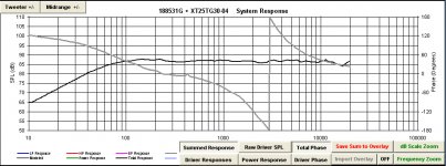
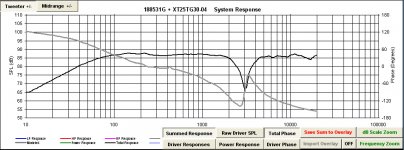
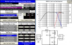
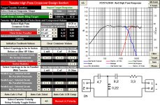
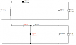
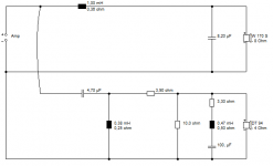
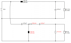
This really needs a complete redesign, including the bass filter. But I had a look at what was DOABLE here without totally binning the 1mH/8.2uF and 4.7uF/0.38mH/5.6R original crossover:
I came up with three options. The first was just lowering the tweeter crossover a tidge and adding the attenuator, which produces about 4dB reduction where it counts at Fs, and a 2dB reduction at 3kHz crossover. There's a thin line in level between glaring fault and minor irritation, so who knows?
Second was an add-on Fs notch. I really don't know if the values are right. Troels (who is top notch himself) has notched at 700 Hz here with an R2604, which should be nearer 440Hz IMO. You'd need to model it with the right FRD and ZMA files to be sure.
Lastly, I used Lozjek's 3rd order filter, more or less, for the tweeter. Without work on the bass filter, phase alignment is scrappy. But Fs level reduction is HUGE. Perhaps 15dB. Adding a simple 2.2R to the bass shunt would help a little to fix the phase.
Well, there it is!
Attachments
- Status
- This old topic is closed. If you want to reopen this topic, contact a moderator using the "Report Post" button.
- Home
- Loudspeakers
- Multi-Way
- Peak/Distortion on a specifik tweeter frequence on homebuild