Driving the bookshelves with the speakers is unlikely to be a good idea because the bookshelves are loosely pinned with a lot of radiating area. I would look to do something like attaching the speakers to the rear wall on rubber bushes or possibly feet that sit on the floor through holes in the bookshelf. Are removable bookshelf sides an option? If so, the speakers can look correct in taking up the full width without being attached to the bookshelf. A thin rubber strip can seal the small gap top and bottom and possibly sides if the bookshelf sides are fixed.The drawing is based on your suggestion to make the walls thinner since they will have support from the bookshelf wall.
12mm looks a bit thin for a largish 3 way cabinet. 18-25mm would be more usual.
Yes, you’re right. My friend would like to be able to crank up the volume occasionally, but we’re not talking about frequent exposure to high SPL.
Okay, but I think that I will go for the partially active setup then, and get either another stereo amp or a new multi-channel. So the drivers will be:
Woofer: 10" SB29NRX75-6
Mid: 5" SB15NRXC30-8
Tweeter: SB29RDNC-C000-4
The TM would actually be the same as Jeff B’s Piccolo, which I have already built. Would his xo be a good starting point for this speaker? I guess that it needs to be changed due to the difference in baffle size as well as off-axis listening position. What would you recommend?
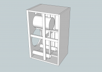
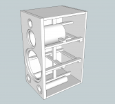
I have made a new SketchUp drawing with updated measurements (the bookshelf has changed slightly since the beginning of this thread). The drawing is based on your suggestion to make the walls thinner since they will have support from the bookshelf wall. The cabinet is now made of 12mm MDF for walls, bracing, and mid enclosure. I can have all the panels for two speakers cut from one sheet, except the baffles which will be 25mm. This give me the following volume:
Volume: 67 L
Midrange: -4.2 L (3.0 L internal)
Bracing: -1.5 L
Ports: -2.0 L
Woofer: -2.0 L
Vb: 57.3 L
I could also change to 16mm for a stronger cabinet with less Vb. What do you think?
I think your friend is going to end up very happy.
")
Baffle diffraction differences mean that the Piccolo xo will need to be changed for your situation. I've already worked up 1 sim for it but why don't you send me the schematic for the Piccolo and I'll use that as a reference point to double check it (out of respect for Jeff and Meniscus, since the schematic is not in the public domain, I'm not going to ask you to post it here). I also looked here for comparison purposes as well - Zaph|Audio - SB12.3 3-Way Tower.
I like your sketch. Three things though.
First, with your cab sitting inside another cabinet, it's not that the other surrounding panels are going to give the speaker walls any structural support (unless you glue or fasten them which is not practical), it's that any sound coming from the speaker walls is going to have to travel through them, and then through all the books etc, or even adjacent cabinet doors too, to get to the listeners ears. Not really going to be significant is it? And maybe a little less so if a thin layer of soft, absorbent material is used between them too.
However, ports don't work as well with very flexy walls (try a ported cardboard enclosure - not so good). So if the speaker walls are thin enough and poorly braced enough, then they may move enough in relation to the changes in air pressure due to large woofer cone movements so that the amount of air going in and out of the port is affected. Sticking with 12mm, I would just add 3 more side to side braces to your design in the middle of each side panel section. Have them tie into your vertical braces too to help prevent the braces from flexing. This is what I would do, but you could go with thicker panels. Again, your call.
Second, it is important to leave enough room between the end of your port and the back wall. Rule of thumb is a distance at least equivalent to the port diameter. And that should probably mean the distance to the back wall and its foam/felt/fiberglass or whatever covering. If the ports are too long, the thing to do is to cut them on a 45* angle, rotate it 180* (I think
 ) and glue them back together for a 90* angle. No difference in function.
 And last, I expect you know this already but it's hard to draw in sketchup. Chamfer (45*) the backsides of your driver cutouts, especially for the mid driver.
Just double checked the closed box Vb for the 15NRXC-8. Add an extra 1.5L or so. It prefers 4.4L for a Qtc of .712 with the walls covered with insulation. A little less if you use a higher density of stuffing but you want to be careful the driver still has enough room behind it to 'breath'.
I was just about to check out on the Falcon website, but thanks to you Andy I’m starting to doubt everything again Joke aside, I appreciate your input of course
The SEAS DXT is also an option. It’s slightly more expensive than the SB29RDNC, but nothing that’s going to break the bank. I’ve attached the manufacturers’ FR. The 30* off-axis does look better on the SEAS. Is it a better tweeter for this application? Will it integrate well with the SB mid and woofer?
I’m not sure what your point is here. That the SPL will never reach “party loud” if the listener is sitting at the dining table? Listening from the dining table will be more for background music than critical listening. Anyway, what’s your proposed solution to your concerns regarding max SPL?
I think these concerns have been the main topic of discussion in this thread. As you say, you believe the position will give more bass boost than jReave or sreten does. If you could point me in the direction of a more “appropriate” simulation tool, I’d be happy to have a look. I have more or less decided to go partly active, meaning that bass and TM will be on separate amps with an electronic xo. This should give me some flexibility and with in-room measurements I think I'll be able to adjust a calibrate until I’ve reached a satisfactory FR.
Look at post #99 where I have changed to ports instead of a slot. The size and lengths of the ports haven’t yet been carefully calculated. I could possibly decrease the port area slightly, which would give me shorter ports, or make 90* angles as suggested by jReave.
Good point about the midrange being too deep for my proposed mid enclosure. I have checked and it should just fit inside the enclosure.
Not sure what you mean by “restricting the area seen by the high frequencies radiating away from the rear of the cone or else they will reflect back”. Regarding back reflections coming back through the cone, I suppose my suggestion for a triangular mid enclosure is better than the traditional square box with a back wall parallel to the cone
Also, I'm not sure how well it shows on the drawings, but I have chamfered the backside of the hole for the midrange.
Thanks for the suggestion, but the SB 10” simulates well in Vb=55L, so I think I will save the money.
Joke aside, I appreciate your input of course The problem is that the layout means you will be listening at approaching 30 degrees off axis where the high frequency SPL is low. As I mentioned earlier, a solution to this is to use a waveguide. The easiest one to use that I am aware of is the SEAS DXT. Compare the output at 30 degress with the tweeters you are currently considering. In addition you get reduced distortion and a clean directivity match with the midrange which becomes more important as the midrange gets larger. An example of how to use the DXT is given here. The example has a less than ideal sensitivity. A more sensitive midrange will need the crossover adjusting and a smaller midrange should cross higher.
The SEAS DXT is also an option. It’s slightly more expensive than the SB29RDNC, but nothing that’s going to break the bank. I’ve attached the manufacturers’ FR. The 30* off-axis does look better on the SEAS. Is it a better tweeter for this application? Will it integrate well with the SB mid and woofer?
Another thing I tried to get across earlier and failed concerned maximum SPL. A speaker with a maximum SPL of 100dB in anechoic conditions would be able to play at the dining table 8m away (-18dB) at a maximum average level (-20dB) of 62dB. The standard/reference listening level is around 80-85dB average where the music is tonally balanced (quieter than this and the highs and lows are missing). Concert and party levels are significantly higher. Thankfully the reflections in the room help the situation by raising the perceived average SPL unless you sit close to the speakers at a desk. In addition serious listening is likely to be done at more like 4m away (-12dB). Maximum SPL, like maximum amplifier power, is all about cleanly handling transients with clean average listening levels being a lot lower.
I’m not sure what your point is here. That the SPL will never reach “party loud” if the listener is sitting at the dining table? Listening from the dining table will be more for background music than critical listening. Anyway, what’s your proposed solution to your concerns regarding max SPL?
Yet another thing I tried to get across without much success was the level of the bass boost. Consider the figure in post #9 here. Relative to a speaker designed for use out in the room like the one shown your speaker will have:
(1) on wall bass boost of 6dB like the one shown although the suckout is likely to be less strong because of the floor and partly filled neighbouring bookshelves and the frequency a bit lower because of a bigger cabinet.
(2) on floor bass boost of 6dB which given the close proximity should be fairly smooth.
(3) near side wall bass boost which is likely to be less smooth. Compare different path lengths and wavelengths for likely location of wiggles.
On top of this you will also have the effects of room modes. This is indicating a significantly geater bass boost than jReave who in turn is suggesting a larger bass boost than sreten. You can either choose who to believe, simulate it yourself using an appropriate tool or choose hardware that will allow you to adjust the design by more than 10dB and take a corresponding hit in overall speaker performance.
I think these concerns have been the main topic of discussion in this thread. As you say, you believe the position will give more bass boost than jReave or sreten does. If you could point me in the direction of a more “appropriate” simulation tool, I’d be happy to have a look. I have more or less decided to go partly active, meaning that bass and TM will be on separate amps with an electronic xo. This should give me some flexibility and with in-room measurements I think I'll be able to adjust a calibrate until I’ve reached a satisfactory FR.
Concerning the cabinet. Ending the slot against back wall will increase the constriction of the slug of air as it moves back and forth and change the tuning. It is probably better to end the slot in more space and have the opportunity to change the length a bit. You might want to consider side slots like this if you are pushed for height with a big midrange.
Look at post #99 where I have changed to ports instead of a slot. The size and lengths of the ports haven’t yet been carefully calculated. I could possibly decrease the port area slightly, which would give me shorter ports, or make 90* angles as suggested by jReave.
Is your midrange cabinet going to foul on the maget? Generally you want avoid restricting the area seen by the high frequencies radiating away from the rear of the cone or else they will reflect back. Chamfering away some of the baffle is also a common thing to do to help with this.
Good point about the midrange being too deep for my proposed mid enclosure. I have checked and it should just fit inside the enclosure.
Not sure what you mean by “restricting the area seen by the high frequencies radiating away from the rear of the cone or else they will reflect back”. Regarding back reflections coming back through the cone, I suppose my suggestion for a triangular mid enclosure is better than the traditional square box with a back wall parallel to the cone
Also, I'm not sure how well it shows on the drawings, but I have chamfered the backside of the hole for the midrange.
If you are pushed for space within the baffle then something like this will match the SB in a significantly smaller volume and with a lower voice coil inductance. It is more expensive though.
Thanks for the suggestion, but the SB 10” simulates well in Vb=55L, so I think I will save the money.
Attachments
Driving the bookshelves with the speakers is unlikely to be a good idea because the bookshelves are loosely pinned with a lot of radiating area. I would look to do something like attaching the speakers to the rear wall on rubber bushes or possibly feet that sit on the floor through holes in the bookshelf. Are removable bookshelf sides an option? If so, the speakers can look correct in taking up the full width without being attached to the bookshelf. A thin rubber strip can seal the small gap top and bottom and possibly sides if the bookshelf sides are fixed.
12mm looks a bit thin for a largish 3 way cabinet. 18-25mm would be more usual.
Thanks for the suggestions. I have previously thought about bolting the speakers to the back wall, but I’m not sure how this would be done in a practical way. The bookshelf will be a fixed instalment, so no sides will be removable. Also, we can’t have special holes for feet to the floor. When my friend decides to move away from this flat, he should be able to take his speakers with him and leave a bookshelf that will work without the speakers, not showing any holes our special arrangements made for the speakers. If the speakers are removed, it would probably make sense to add horizontal shelves to the shelving unit where the speakers used to be.
I’m thinking about making the cabinets 2cm less wide and high compared to the shelving unit, and then add some kind of material between speaker and bookshelf, something like cork, foam, rubber or polystyrene.
Sorry, but look at those 2 FR graphs above again. It doesn't make any sense at all in an application where HF loss is critical to suggest using a tweeter that has smaller 30* deviation (and it's only smaller by a very tiny degree) when the fundamental starts dropping like a stone at 5kHz. And below are the harmonic distortion plots for the 2 tweeters. I haven't labelled them. Which one is actually superior for a xo around 1.8-2kHz? For a casual listener, it probably won't make any difference, although I would pick the 2nd.
Attachments
I think your friend is going to end up very happy.
I think and hope so too!
Baffle diffraction differences mean that the Piccolo xo will need to be changed for your situation. I've already worked up 1 sim for it but why don't you send me the schematic for the Piccolo and I'll use that as a reference point to double check it (out of respect for Jeff and Meniscus, since the schematic is not in the public domain, I'm not going to ask you to post it here). I also looked here for comparison purposes as well - Zaph|Audio - SB12.3 3-Way Tower.
I will email the Piccolo schematics to you.
By the way, that 3-way tower by Zaph uses the ferrite magnet SB29RDC while the Piccolo uses the neodymium SB29RDNC. Specs and FR differ only slightly and they cost about the same. Which would you recommend here?
I like your sketch. Three things though.
First, with your cab sitting inside another cabinet, it's not that the other surrounding panels are going to give the speaker walls any structural support (unless you glue or fasten them which is not practical), it's that any sound coming from the speaker walls is going to have to travel through them, and then through all the books etc, or even adjacent cabinet doors too, to get to the listeners ears. Not really going to be significant is it? And maybe a little less so if a thin layer of soft, absorbent material is used between them too.
I see what you mean.
However, ports don't work as well with very flexy walls (try a ported cardboard enclosure - not so good). So if the speaker walls are thin enough and poorly braced enough, then they may move enough in relation to the changes in air pressure due to large woofer cone movements so that the amount of air going in and out of the port is affected. Sticking with 12mm, I would just add 3 more side to side braces to your design in the middle of each side panel section. Have them tie into your vertical braces too to help prevent the braces from flexing. This is what I would do, but you could go with thicker panels. Again, your call.
I understand. I will update the drawing with the increased volume for the mid, and also do some calculations on the total Vb using 12mm and 16mm panels.
Second, it is important to leave enough room between the end of your port and the back wall. Rule of thumb is a distance at least equivalent to the port diameter. And that should probably mean the distance to the back wall and its foam/felt/fiberglass or whatever covering. If the ports are too long, the thing to do is to cut them on a 45* angle, rotate it 180* (I think
Gotcha!
And last, I expect you know this already but it's hard to draw in sketchup. Chamfer (45*) the backsides of your driver cutouts, especially for the mid driver.
Yes, I know. I did it to the mid, but it’s hard to see on the SU drawings. I’m using the “Round Corner” plugin, which removes the line edges when chamfering.
Thanks - got the schematic.
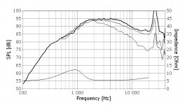
Re the 29RDC vs the 29RDNC, 1st 2 graphs below are their FR's. Not much difference. The RDNC might be a little flatter.
Next 2 charts show harmonic distortion. I'm not sure if you're familiar with these, some people have a hard time reading them at first. Third and 5th order are the most dissonant and therefore the most unpleasant (blue and grey lines respectively). 29RDC first again and then the 29RDNC. The 3rd order distortion for the 29RDNC is peaking a little higher just below 2kHz. If the xo is at 3kHz, it won't make much of a difference. When the xo is closer to 2kHz, you may hear it a tiny bit more. If you're an audiophile and are listening for it. Not enough difference in the CSD graphs to post them.
You might hear a difference between the 2 of them but I'm not sure that you might call 1 of them better than the other. I have not heard either. Reading on-line, both are well praised. Flip a coin. Unless someone with personal experience with both wishes to weigh in.
Attachments

Whether it is a better tweeter is for you to decide. The primary purpose of the waveguide is to control directivity and match the directivity of the mid and tweeter at crossover. You can see this in the example design. For a tweeter without a waveguide there is a jump in directivity between the tweeter and mid. This results in a step change in the frequency response of a substantial proportion of the reflected sound.Is it a better tweeter for this application? Will it integrate well with the SB mid and woofer?
I am not proposing a solution. I was trying to get you to rough out what maximum SPL at 1m you would need to avoid clipping transients at standard listening levels.Anyway, what’s your proposed solution to your concerns regarding max SPL?
An example of free software to solve the 3D scalar wave equation is here but there are others.If you could point me in the direction of a more “appropriate” simulation tool, I’d be happy to have a look. I have more or less decided to go partly active, meaning that bass and TM will be on separate amps with an electronic xo. This should give me some flexibility and with in-room measurements I think I'll be able to adjust a calibrate until I’ve reached a satisfactory FR.
If the crossover is programmable an active solution will be more flexible but also more expensive. It also cannot overcome some potential poor choices such as opting for a midrange that cannot work low enough.
The simulation programs are not exact and experienced designers often opt for ports somewhat longer than that for maximum bass extension. I would suggest going for an arrangement that allows you to modify the length based on what you find.The size and lengths of the ports haven’t yet been carefully calculated. I could possibly decrease the port area slightly, which would give me shorter ports, or make 90* angles as suggested by jReave.
The best shape is probably a cylinder with a bulge to get round the magnet while maintaining a constant(ish) cross sectional area and then gently tapering down. A square box with a cross section at the magnet slightly greater than that of the cone is likely to be OK. What you want to avoid is a sharp change in cross sectional area in the direction the rear wave is propagating because this will reflect the sound. I am not sure I can see the purpose of the current shape since a normal tube or box may well give a longer path length through the dissipating material before what is left of the sound returns to the cone. But I doubt this sort of thing is of great importance so long as the chamber is appropriately stuffed.Not sure what you mean by “restricting the area seen by the high frequencies radiating away from the rear of the cone or else they will reflect back”. Regarding back reflections coming back through the cone, I suppose my suggestion for a triangular mid enclosure is better than the traditional square box with a back wall parallel to the cone
Why throw away all that volume? What is wrong with a gap of a few mm? If you seal the entrance with a soft rubber strip what is the purpose of putting material between the bookshelf and the speaker?I’m thinking about making the cabinets 2cm less wide and high compared to the shelving unit, and then add some kind of material between speaker and bookshelf, something like cork, foam, rubber or polystyrene.
I think you may misunderstand how a waveguide+tweeter is used. Look at the speaker example and you will see a flat response and a small modification in the crossover to get it.Sorry, but look at those 2 FR graphs above again. It doesn't make any sense at all in an application where HF loss is critical to suggest using a tweeter that has smaller 30* deviation (and it's only smaller by a very tiny degree) when the fundamental starts dropping like a stone at 5kHz.
I don't know how those plots were taken but are you comparing apples with apples? The lower voltage applied to the waveguide+tweeter over the more efficient low frequency region reduces the deflection of the cone and hence the distortion compared to the higher frequency range.And below are the harmonic distortion plots for the 2 tweeters. I haven't labelled them. Which one is actually superior for a xo around 1.8-2kHz? For a casual listener, it probably won't make any difference, although I would pick the 2nd.
I’m thinking about making the cabinets 2cm less wide and high compared to the shelving unit, and then add some kind of material between speaker and bookshelf, something like cork, foam, rubber or polystyrene.
Yes, I concur. I read this over too fast and thought it was 2mm. You want to make the space between the speaker, the softer layer and the shelving cabinet walls as tight as possible. Tight enough that you need vaseline to slip them in.
Just kidding. Sort of. So you don't need the softer layer to be 2cm. I would think 2 to 4mm would be fine.
Whether it is a better tweeter is for you to decide. The primary purpose of the waveguide is to control directivity and match the directivity of the mid and tweeter at crossover. You can see this in the example design. For a tweeter without a waveguide there is a jump in directivity between the tweeter and mid. This results in a step change in the frequency response of a substantial proportion of the reflected sound.
And that’s not an easy decision to make since I have no experience with waveguides. On the contrary I already know the SB29RDNC from my current speakers and I really like their sound, even off-axis.
I have read up on waveguides, trying to understand how they work and what benefits they have. Waveguides do indeed help to control the directivity of the higher frequency, which means better off-axis response. But waveguides also give a rise in the FR, the “waveguide hump”, which I assume you will have to deal with somehow? Zaph has a page discussing waveguides here. I have searched for opinions on the SEAS DXT and from what I’ve found people don’t seem overly impressed by it, see e.g. this PE thread.
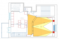
I have looked at the floor plan and speaker placement I tried to illustrate the horizontal off-axis response, see attached drawing showing 15* and 30* off-axis. If you believe off-axis response is a great concern for this project I guess there are other candidates to consider, e.g. metal dome tweeters such as Vifa NE19-VTA or SB26ADC. Again, I’m not sure how well either of those would integrate with the SB mid and woofer. The SB29RDNC+SB15NRXC30-8 OTOH is a tried and tested combination.
The simulation programs are not exact and experienced designers often opt for ports somewhat longer than that for maximum bass extension. I would suggest going for an arrangement that allows you to modify the length based on what you find.
Good idea. I have looked at these ports from Monacor, which are adjustable. Two of those will give me an area of 40.8 cm2. Do you think that’s enough for the 10” SB?
The best shape is probably a cylinder with a bulge to get round the magnet while maintaining a constant(ish) cross sectional area and then gently tapering down. A square box with a cross section at the magnet slightly greater than that of the cone is likely to be OK. What you want to avoid is a sharp change in cross sectional area in the direction the rear wave is propagating because this will reflect the sound. I am not sure I can see the purpose of the current shape since a normal tube or box may well give a longer path length through the dissipating material before what is left of the sound returns to the cone. But I doubt this sort of thing is of great importance so long as the chamber is appropriately stuffed.
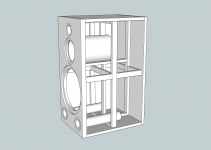
I have looked at using large diameter PVC tube instead. See the attached drawing with a 160mm tube. Internal volume is now a little over 4L. Last picture is a view from inside the tube showing a 10mm chamfer on hole for the mid.
Why throw away all that volume? What is wrong with a gap of a few mm? If you seal the entrance with a soft rubber strip what is the purpose of putting material between the bookshelf and the speaker?
So you would only put absorbing material in the gaps around the front of the speaker? I thought I would need to have material on all the surface between the speakers and the bookshelf to avoid having two hard surfaces touching each other.
Anyway, I have updated the dimensions of the speaker. It is now only a tiny bit smaller than the shelving unit, just 2mm all the way around. I have also changed to 16mm MDF and simplified the bracing. The updates give my the following Vb calculations:
Volume: 69 L
Midrange: -4.5 L (4 L internal)
Bracing: -2.3 L
Ports: -2.0
Woofer: -2.0
Vb: 58.2
Thoughts?
Attachments
A couple of questions.
I'm wondering if the listening room actually has a couch or a chair in it across from the speakers that would be a central listening spot if and when your friend ever wants to sit down to enjoy the music. If so, then what is that distance? I ask because that is the position I would model the xo for.
Also, at the risk of creating more decisions, I haven't used an active xo but I'm assuming that if you use one that you can eq the bottom end. If this is the case, then we no longer have to work with the same set of restrictions that were in place in originally selecting the woofer (that only took me a few days to figure out sheesh). In other words, you can choose a woofer of different sensitivity and impedance if you want and you could possibly run it sealed and then eq the bottom end to taste. This will eliminate the problem of port tuning and could result in a less expensive woofer and/or amp (smaller power requirement to reach the same SPL with a higher sensitivity driver). Also volume constraints could be relaxed and you get the benefit of what some people consider to be better bass with a sealed box.
The SB29 actually works sealed in 30L to 104dB/1m with 70W before exceeding xmax.
The Peerless 10" works sealed in 45-50L to 104.5dB with 40W.
And looking at what else Falcon had available,
the Seas CA26RE4X 10" will work sealed in 25-30L to 108dB with 50W. http://www.falconacoustics.co.uk/downloads/Seas/h1316_datasheet.pdf
All require eq though to effectively replace what the ports would be doing. Both alternatives to the SB are less expensive btw.
I have worked out xo's for the SB15NRXC-8 and both the 29RDC and the 29RDNC. Both combinations go together more easily and more simply than with the 17NRXC-4 and are very very similar in response and in values. I'll post them shortly. Personally I would stick with either of these tweeters - I've just been hearing so many good things about them lately and their off-axis responses are actually quite good. If making the choice, I would go with the 29RDC because of the slightly lower distortion and the more symetrical impedance response. Perfectionist stuff.
I do actually agree with andy about the mid enclosure and think the 160mm tube would be an improvement. About 4.5L internal with heavy stuffing in the back half or 2 thirds should work nicely. I actually tend to like to give the mid even more room, so Qtc a little lower, but that might be tough to do in your case. Depends on your above decision.
Your bracing was better before. Turn them back 90* so the longer axis is perpendicular to the panels again. More stiffness.
I'm wondering if the listening room actually has a couch or a chair in it across from the speakers that would be a central listening spot if and when your friend ever wants to sit down to enjoy the music. If so, then what is that distance? I ask because that is the position I would model the xo for.
Also, at the risk of creating more decisions, I haven't used an active xo but I'm assuming that if you use one that you can eq the bottom end. If this is the case, then we no longer have to work with the same set of restrictions that were in place in originally selecting the woofer (that only took me a few days to figure out
sheesh). In other words, you can choose a woofer of different sensitivity and impedance if you want and you could possibly run it sealed and then eq the bottom end to taste. This will eliminate the problem of port tuning and could result in a less expensive woofer and/or amp (smaller power requirement to reach the same SPL with a higher sensitivity driver). Also volume constraints could be relaxed and you get the benefit of what some people consider to be better bass with a sealed box.The SB29 actually works sealed in 30L to 104dB/1m with 70W before exceeding xmax.
The Peerless 10" works sealed in 45-50L to 104.5dB with 40W.
And looking at what else Falcon had available,
the Seas CA26RE4X 10" will work sealed in 25-30L to 108dB with 50W. http://www.falconacoustics.co.uk/downloads/Seas/h1316_datasheet.pdf
All require eq though to effectively replace what the ports would be doing. Both alternatives to the SB are less expensive btw.
I have worked out xo's for the SB15NRXC-8 and both the 29RDC and the 29RDNC. Both combinations go together more easily and more simply than with the 17NRXC-4 and are very very similar in response and in values. I'll post them shortly. Personally I would stick with either of these tweeters - I've just been hearing so many good things about them lately and their off-axis responses are actually quite good. If making the choice, I would go with the 29RDC because of the slightly lower distortion and the more symetrical impedance response. Perfectionist stuff.
I do actually agree with andy about the mid enclosure and think the 160mm tube would be an improvement. About 4.5L internal with heavy stuffing in the back half or 2 thirds should work nicely. I actually tend to like to give the mid even more room, so Qtc a little lower, but that might be tough to do in your case. Depends on your above decision.
Your bracing was better before. Turn them back 90* so the longer axis is perpendicular to the panels again. More stiffness.
Let me just address directivity for a second. First attachment below tries to show in graphical terms what the horizontal directivity looks like for each of the SB drivers you're looking at. With the mid/tweeter xo at 2Khz and with a 4th order acoustic slope, the continuity of off-axis behavior as one driver hands off to the other is excellent. Thirty degrees off-axis for the whole speaker with xo's does not in fact drop below the on-axis response by any significant degree until up around 10kHz. If your ears tell you to, you can lower the padding a touch on the tweeter if you think it sounds better.
The next chart is what your Piccolo looks like when I sim it with the files available to me. That looks pretty good and is a useful standard of comparison when looking at the next sims with your baffle dimensions. For these I used the center of the tweeter at about 7.6 to 9cm below the top of your shelving unit and they are based on a listening axis that is 2.5m away, 25cm above the middle of the tweeter and about 20* horizontally off-axis, which would be a seated position in between the speakers. I haven't included the driver phases because they get so messy at these listening angles but you can see how well they align by the good reverse nulls in each graph.
The last attachment shows the xo values for each tweeter and mid. I can post them as schematics and let you know which values you might want to change in terms of voicing it if you like. There is quite a difference between these values and what the Piccolo uses which is what you should expect with such a huge difference in baffle configuration and placement.
(Second chart is mislabeled - the SB29NRX30-8 should be 15NRXC30-8. This is the Piccolo.)
Cheers
Attachments
I think I need to amend my sealed woofer suggestion.
I forgot to include the extra amp power that you need in order to do the LF boosting. So with the Peerless 10" for eg, it will need about 6-8dB of boost at about 25Hz to reach the same level as the SB29RNX ported at 25Hz. So that's 40W doubled at least twice again, so 80W and then 160W plus headroom if you want to make it work at those SPL levels. And it's only rated at 140W max. The Seas needs even a little more boost than that. Probably best to stick with the SB ported. Oh well........
I forgot to include the extra amp power that you need in order to do the LF boosting. So with the Peerless 10" for eg, it will need about 6-8dB of boost at about 25Hz to reach the same level as the SB29RNX ported at 25Hz. So that's 40W doubled at least twice again, so 80W and then 160W plus headroom if you want to make it work at those SPL levels. And it's only rated at 140W max. The Seas needs even a little more boost than that. Probably best to stick with the SB ported. Oh well........
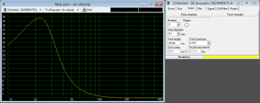
It looks to be in the right ball park. Air velocities look OK for longer port lengths with a conservative high pass filter but perhaps a bit marginal for shorter port lengths.I have looked at these ports from Monacor, which are adjustable. Two of those will give me an area of 40.8 cm2. Do you think that’s enough for the 10” SB?
I am not sure I understand. The speaker is probably best attached to the rear wall or floor via rubber isolators without touching the bookshelf anywhere. A soft rubber ring or felt can used to keep air out of the cavity and keep a smooth baffle surface. Putting some fibreglass or speaker damping material in a significant sized cavity might be a good idea but it should avoid transferring the vibrations of the speaker walls to the bookshelf.So you would only put absorbing material in the gaps around the front of the speaker? I thought I would need to have material on all the surface between the speakers and the bookshelf to avoid having two hard surfaces touching each other.
I'm wondering if the listening room actually has a couch or a chair in it across from the speakers that would be a central listening spot if and when your friend ever wants to sit down to enjoy the music. If so, then what is that distance? I ask because that is the position I would model the xo for.
Yes. There will be an ottoman placed in the living room, almost in centre of the speakers, about 3.5 meters away. This spot will be 21* horizontally off-axis. By the way, we have to move the right speaker one shelving unit to the right as there are some radiator pipes that would otherwise limit the depth of the speakers. The centre of right speaker is now 56 cm away from the right wall while the centre of the left speaker is 78 cm away from the left wall.
I do actually agree with andy about the mid enclosure and think the 160mm tube would be an improvement. About 4.5L internal with heavy stuffing in the back half or 2 thirds should work nicely. I actually tend to like to give the mid even more room, so Qtc a little lower, but that might be tough to do in your case. Depends on your above decision.
Your bracing was better before. Turn them back 90* so the longer axis is perpendicular to the panels again. More stiffness.
Okay, I have increased to mid volume to 4.5 and changed the bracing slightly. See attached drawing. I save a little volume on the bracing but loose some on the mid. Vb is still around 58 L.
Let me just address directivity for a second. First attachment below tries to show in graphical terms what the horizontal directivity looks like for each of the SB drivers you're looking at. With the mid/tweeter xo at 2Khz and with a 4th order acoustic slope, the continuity of off-axis behavior as one driver hands off to the other is excellent. Thirty degrees off-axis for the whole speaker with xo's does not in fact drop below the on-axis response by any significant degree until up around 10kHz. If your ears tell you to, you can lower the padding a touch on the tweeter if you think it sounds better.
That looks good to me
The next chart is what your Piccolo looks like when I sim it with the files available to me. That looks pretty good and is a useful standard of comparison when looking at the next sims with your baffle dimensions. For these I used the center of the tweeter at about 7.6 to 9cm below the top of your shelving unit and they are based on a listening axis that is 2.5m away, 25cm above the middle of the tweeter and about 20* horizontally off-axis, which would be a seated position in between the speakers. I haven't included the driver phases because they get so messy at these listening angles but you can see how well they align by the good reverse nulls in each graph.
Thanks for the help! That looks really good. If we take the driver layout from the attached drawing, the centre of the tweeter is going to be 9.5cm below the top of the shelving unit (and 8.3cm below the bottom of the top, which is 12mm and sticks out 10mm). The centre-to-centre distance between tweeter (29RDNC) and mid is 12cm. If the 29RDC is used these measurements may change slightly. I think we should just stick with the 29RDNC.
The last attachment shows the xo values for each tweeter and mid. I can post them as schematics and let you know which values you might want to change in terms of voicing it if you like. There is quite a difference between these values and what the Piccolo uses which is what you should expect with such a huge difference in baffle configuration and placement.
Please do! That would be very helpful. Looks like this project is getting closer to being realised
This is all very exiting! I promise to post many photos when I start to build.Attachments
It looks to be in the right ball park. Air velocities look OK for longer port lengths with a conservative high pass filter but perhaps a bit marginal for shorter port lengths.
I did some WinISD sims and with the two Monacor ports I get a max air velocity of almost 38 m/s (123 ft/s) at 135W input, which is where cone excursion reaches Xmax. Will these ports chuff if the volume is cranked up?
Attachments
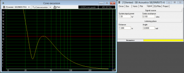
Your cone excursion plot goes off the scale and so playing some film rumblings is likely to break the driver. For ported speakers what is normally done is to include a high pass filter to bring the cone excursion back to safe levels. This will reduce the maximum air velocity as will lengthening the port. Chuffing is also reduced by flaring the ends. Some measurements to help gauge what is likely to chuff can be found here and other places on the web.I did some WinISD sims and with the two Monacor ports I get a max air velocity of almost 38 m/s (123 ft/s) at 135W input, which is where cone excursion reaches Xmax. Will these ports chuff if the volume is cranked up?
If peak velocities are at, say, 20Hz and you are listening to conventional music then nothing is going to be driving the speakers to maximum SPL at this frequency. This is not necessarily the case with films and some non-conventional music.
I seem to have chopped off the first part of my reply in an earlier post.
Reading forum posts requires a degree of interpretation. There is good advice and there is bad advice. Sorting out which is which when the subject is relatively new to you can be difficult. Now there is criticism in the cited thread but there is also criticism of the criticism. How to weight the contributions?
The DXT was suggested because it was the simplest way to get a waveguide. If you do not believe a waveguide will bring significant benefits to the project then the DXT is unlikely to be a good choice. The use of sharp edges to aid the diffraction creates a small package but almost all high quality commercial speakers with waveguides have a larger smooth walled elliptical shape. There are reasons for this.
The first design decision concerning tweeter/midrange integration is waveguide or no waveguide. The choices you would make after this are likely to be different. If you opt for no waveguide I am not sure why you are considering the tweeters you cite if you already like the tweeter you have used before.
And that’s not an easy decision to make since I have no experience with waveguides. On the contrary I already know the SB29RDNC from my current speakers and I really like their sound, even off-axis.
I have read up on waveguides, trying to understand how they work and what benefits they have. Waveguides do indeed help to control the directivity of the higher frequency, which means better off-axis response. But waveguides also give a rise in the FR, the “waveguide hump”, which I assume you will have to deal with somehow? Zaph has a page discussing waveguides here. I have searched for opinions on the SEAS DXT and from what I’ve found people don’t seem overly impressed by it, see e.g. this PE thread.
Reading forum posts requires a degree of interpretation. There is good advice and there is bad advice. Sorting out which is which when the subject is relatively new to you can be difficult. Now there is criticism in the cited thread but there is also criticism of the criticism. How to weight the contributions?
The DXT was suggested because it was the simplest way to get a waveguide. If you do not believe a waveguide will bring significant benefits to the project then the DXT is unlikely to be a good choice. The use of sharp edges to aid the diffraction creates a small package but almost all high quality commercial speakers with waveguides have a larger smooth walled elliptical shape. There are reasons for this.
What does integration between tweeter and midrange mean to you? Does the tweeter+midrange in your 3 way project require the same design decisions as a tweeter+midwoofer in a 2 way? Think about efficiency, bass extension, cone displacement, directivity and the like.I have looked at the floor plan and speaker placement I tried to illustrate the horizontal off-axis response, see attached drawing showing 15* and 30* off-axis. If you believe off-axis response is a great concern for this project I guess there are other candidates to consider, e.g. metal dome tweeters such as Vifa NE19-VTA or SB26ADC. Again, I’m not sure how well either of those would integrate with the SB mid and woofer. The SB29RDNC+SB15NRXC30-8 OTOH is a tried and tested combination.
The first design decision concerning tweeter/midrange integration is waveguide or no waveguide. The choices you would make after this are likely to be different. If you opt for no waveguide I am not sure why you are considering the tweeters you cite if you already like the tweeter you have used before.
The box program I use suggests that port noise is likely to become noticeable somewhere between 17 and 26m/s depending on flaring or no flaring. Your eg is up at 38m/s. Too high. If you really want to play loud, you may need to go with a slightly larger port diameter.
Port length with those Monacors will be fine as long as you are able to fine tune the LF with whatever active xo you choose to go with. Typically when tuning down this low, you might want to tune a little lower than usual to avoid boomy bass due to room gain so that means longer ports than those Monacors. So with those ports, you might actually have to pull the response down just a touch around 30 or 40Hz. You'll have to listen and/or measure to know for sure.
And if you can also use a HP filter at about 20Hz on the woofer, that will help to control those very high cone excursions down at those frequencies at large SPL's.
What I was sort of thinking was that you could actually use damping material around the outside of the speaker cabinets, perhaps something like this - BITUMEX/FG2 - BITUMEX FG 2 SK 245 x 325 x 2,0 mm - Europe Audio - to decrease resonances and sound transmission but given that there's another set of panels surrounding them, I'm not sure that it's 100% necessary. I'd probably do it if I could find something that wasn't too expensive. Otherwise a strip or 2 of something like felt all around the front perimeter to seal it off and then just small pieces elsewhere to prevent wood to wood contact might be sufficient.
- Status
- This old topic is closed. If you want to reopen this topic, contact a moderator using the "Report Post" button.
- Home
- Loudspeakers
- Multi-Way
- 3-way for bookshelf (in-wall)