I debated somewhat where to go about posting this, as it is a complete digital system in its own right, but figured here'd be most appropriate. Most of the system design, rather than anything else is after-all tailored towards getting the loudspeakers doing what they should be doing.
This project started after a room in the house was available for re-purposing and subsequently one side of it turned into a dedicated workspace where I can now build and test electrical bits and bobs in peace 😀 Naturally the room needed a sound system of some sort, so this project was born.
Small was a number one requisite, as space was very limited and as I would be sitting up close to the loudspeakers (between 30-50cm) and at a varying degree of off axis angles, driver integration and the off axis response were also important.
A while ago CJD, over on the htguide forums, posted about a tiny little speaker he'd designed called the Pecorino http://www.htguide.com/forum/showthread.php?39093-The-Pecorinos. Here he'd used a small, cast, aluminium box by Hammond for the main enclosure, only replacing the front with plywood as a suitable foundation for mounting the drivers. I thought this was a rather clever idea as it would reduce the amount of work needed to make the cabinet. It would also, due to the thin aluminium side walls, increase the overall net volume of the enclosure when compared to making the cabinet out of MDF. Hammond also manufacture these finished in an attractive matt black, which is a lot nicer to look at than the raw aluminium.
My idea at first was to use a small full range drive unit, sans tweeter, as this would be the simplest route to go down, but upon auditioning the Vifa TG9 solo, it was clear that something was missing and a tweeter was added.
Why the TG9 and not the TC9 as measured by Zaph? First of all the TG9 was easier to get hold of, as Europe-Audio actually stocked them. And second, the white fibreglass cone matched the rest of the design a little better.
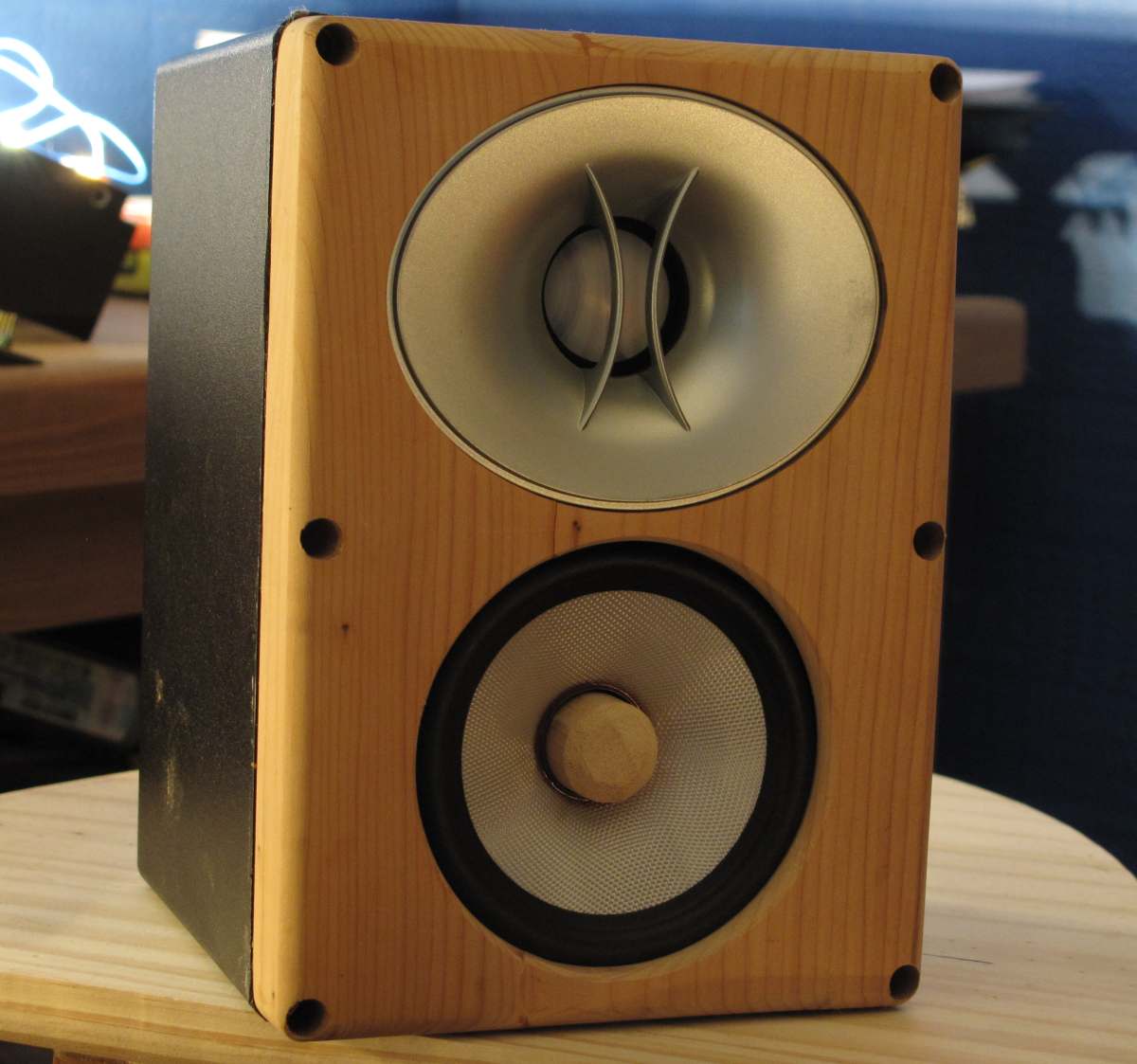
The tweeter, if necessary, that I had intended to use, was an Ebay buy from China. I bought these over a year ago as a surplus amount of OEM devices intended for Infinity. These were a pair of their so called 'CMMD' tweeters mounted in a small, horizontally biased wave-guide and finished in silver – hence preferring the white cone of the Vifa. Also as the front baffle was to be made out of Yew, the white cone again, better matched the light tone of the wood. The tweeters cost less than £15 for the pair, including shipping, which was a bit of a bargain!
The first place to start mind was with the cabinets. These aluminium boxes are nice, but they ring like a bell and need some sort of treatment. I used a combination of thin sheets of plywood, hot-melt glue and some dowelling. Hot-melt glue is perfect for this as it sets rather soft and dampens the ringing down quite effectively, even on its own.
In these two picture you can see exactly how this was done + the mounted xover components. These were also glued down and add additional mass to help dampen cabinet ringing even further.
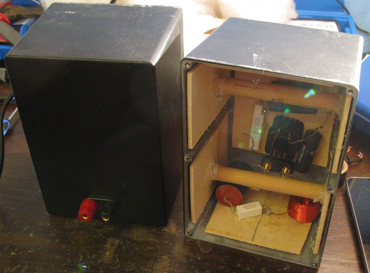
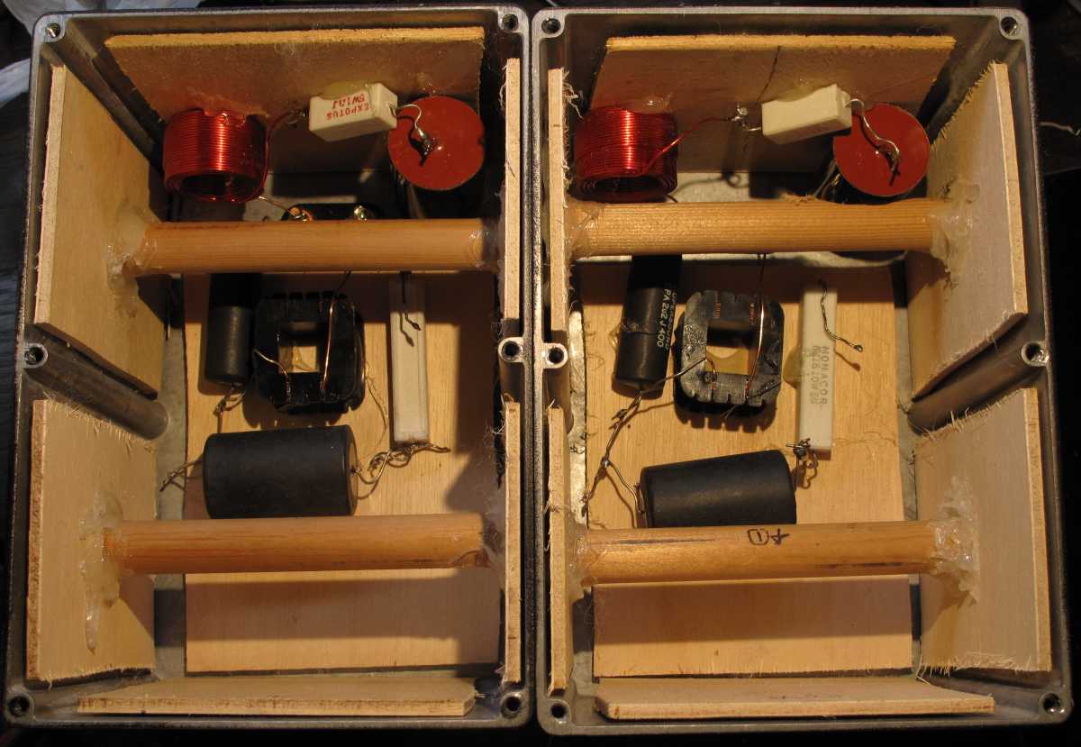
As you can see the cabinets already have 6 pre-tapped holes ready to accept counter-sunk screws that are also provided. This makes attaching a front baffle, as opposed to the boxes lid, very easy, but before doing so I placed a strip of self-adhesive weather sealing foam around the front baffle. This ensures that the gap between the cabinets and the baffle is air tight, but also decouples the baffle from the box and dampens the aluminium box even further.
Once constructed the speakers were ready for measuring.
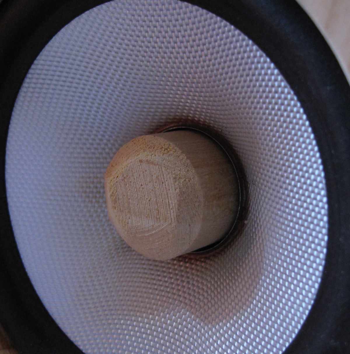
First you will probably notice that the standard black dust-cap is no more. When I first measured the drivers I was a little let down at the performance of the TG9. Having seen how the TC9 performed in Zaph's measurements, I had high hopes for this driver, but in its stock configuration it wasn't to be. When performing a distortion sweep at 2.8v, below 1kHz, both the third and fifth harmonics sharply rose to above 1% before rising again towards low frequencies. This didn't seem right as the behaviour didn't match up with how drivers typically perform, at least in terms of motor linearity, so I took the baffle off and started to have a play. What I quickly discovered was that most of the offending crud was being shoved out of the pole vent. Now at 500Hz etc we're not going to be encountering problems due to the pole vent being too narrow so I can only assume that some sort of resonances were occurring within the chamber behind the dust-cap and within the pole vent itself. Needless to say I got out the scalpel and very carefully removed the dust-cap. Luckily it was glued in place with glue similar to the stuff they affix credit cards to letters with, so it peeled away from the cone rather easily.
By sheer luck, the pole vent was just larger than an M6 bolt, of which I had many and plenty of bolt inserts designed to screw into wood too. Here is a picture of the rear of the TG9 with a bolt shoved through the pole vent.
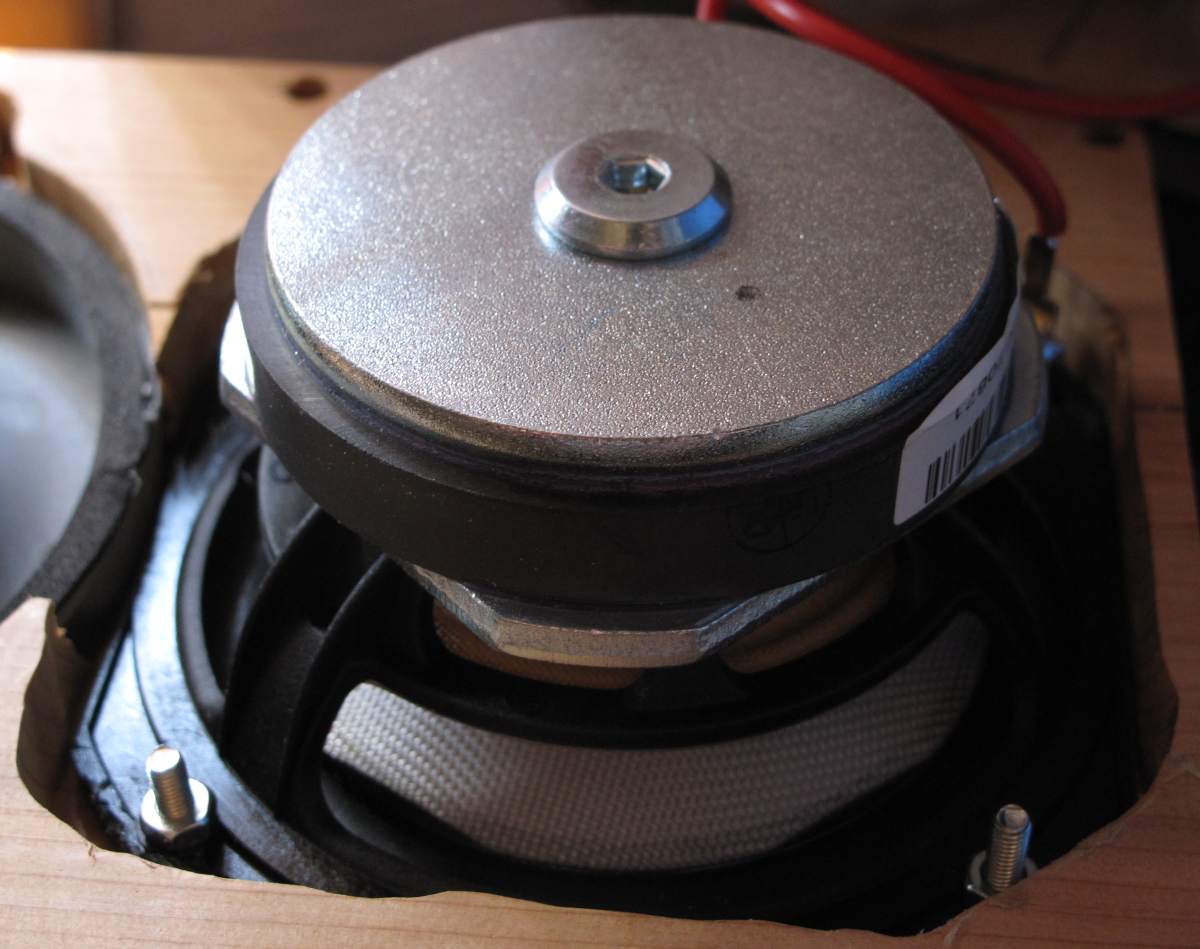
I bought some 18mm rods, cut them to length, screwed in an insert and then screwed the hand crafted phase plugs into place. Thankfully this completely solved the distortion problem. I do not know how Zaph measured the TC9, but at low levels this problem did get significantly better. Why companies bother with dust-caps, I don't know as they seem to create more problems than they solve. This isn't universally true mind you, but in an inexpensive driver, where a lot of time cannot be spent in optimising the dust-cap and the pole vent, you'd think it would make more sense to throw in an off the shelf phase plug.
Having modified the drivers it was now time to measure the drivers and design a passive crossover. Given the wave-guide on the tweeter I had hoped to be able to get away with a 2nd order acoustic target between 3 and 4kHz, but it wasn't to be, the phase tracking simply didn't work so I switched over to a 4th order target and everything fell into place. I was quite surprised to find that even with the TG9s wide bandwidth I only needed a 2nd order electrical to hit a 4th order target. This was very welcome as I wanted to keep the xover cost down to a minimum. After having finalised the design I got my bag of surplus xover components and with some optimising in LspCAD I found that I actually had all the parts necessary, which was even more welcome. The only thing I needed to do was unwind one inductor a little and everything was set. I measured the tweeters individual distortion performance and they would easily support a 4th order at 2.5kHz, but unfortunately I do not have these measurements saved.
Here are the xover schematics.
And here is the frequency response. The black line is the predicted, simulated, response and the grey line is the actual measured response. Quite clearly they match very well, which is always nice to see.
Now I hear you crying, but wait, 5th element, that's hardly a particularly nice looking frequency response graph, are you mad?! Perhaps, but this leads us nicely onto the next part of the design, the electronics.
The source of this little system is in fact a first gen. Nexus 7 tablet by google. This device lives on the workbench and serves as a way of easily displaying data-sheets etc when I am soldering, but it also serves as a music server. Now cables here are not particularly helpful as they just get in the way and the audio out on the tablet, although decent, is nothing to write home about. So I needed another option. The answer here was to use the RN52 bluetooth module by Microchip.
This nifty little device outputs a balanced audio stream, but it also outputs a digital signal. It is supposed to output I2S, but this does not work as intended. Thankfully the S/PDIF output does work.
Here you can see a little PCB that receives bluetooth at one end and outputs an analogue signal at the other.
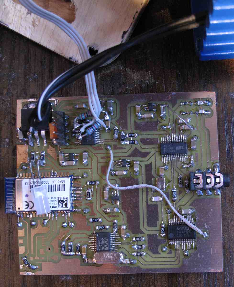
This includes the bluetooth module, a Wolfson WM8804 S/PDIF receiver, a SRC4192 asynchronous sample rate converter, a PCM5142 DAC from TI and a PIC24F32KA301 micro controller from Microchip.
I figured it made sense to add in the SRC because I cannot imagine the bluetooth module having a terrific quality S/PDIF output and through up-sampling this also shifts the interpolation filter in the DAC further out of the audio band. I set the SRC to output a 96kHz signal.
The DAC is a more flexible version of the PCM5102, which has made the rounds on DIYaudio before I believe. It incorporates a charge pump, to generate a negative voltage rail and internal I/V opamps so that it can output a ground centred 2.1VRMS output. This is very useful in reducing the design complexity as it will work from a single 3.3v rail, but the biggest difference between the 02 and 42 is that the 42 has a fully configurable miniDSP on board – now you can see why the crap frequency response doesn't look as bad any more 🙂
The goal of the passive crossover was to basically knit the two drivers together at a suitable xover frequency with good phase tracking. If you look back at the frequency response graph you will see that zero baffle step compensation is applied, the tweeter has a rising response and there's a horrible lump at 1800Hz due to diffraction. Not only this, but that little Vifa has a terribly high Qtc and when placed in a small box like this, it rises even more. You end up with a final system Q of around 1.2 at ~160Hz, this is not ideal.
The DSP was configured to provide this equalisation curve.

As you can see this sorts out most of the problems and adds in a Linkwitz Transform circuit + highpass to sort out the low frequency response. Now, no one is going to expect a tiny little driver to do much down low, but as these are near-field monitors, used at low listening levels, I figured I'd rather have a bit more extension.
Part two coming in a few 🙂
This project started after a room in the house was available for re-purposing and subsequently one side of it turned into a dedicated workspace where I can now build and test electrical bits and bobs in peace 😀 Naturally the room needed a sound system of some sort, so this project was born.
Small was a number one requisite, as space was very limited and as I would be sitting up close to the loudspeakers (between 30-50cm) and at a varying degree of off axis angles, driver integration and the off axis response were also important.
A while ago CJD, over on the htguide forums, posted about a tiny little speaker he'd designed called the Pecorino http://www.htguide.com/forum/showthread.php?39093-The-Pecorinos. Here he'd used a small, cast, aluminium box by Hammond for the main enclosure, only replacing the front with plywood as a suitable foundation for mounting the drivers. I thought this was a rather clever idea as it would reduce the amount of work needed to make the cabinet. It would also, due to the thin aluminium side walls, increase the overall net volume of the enclosure when compared to making the cabinet out of MDF. Hammond also manufacture these finished in an attractive matt black, which is a lot nicer to look at than the raw aluminium.
My idea at first was to use a small full range drive unit, sans tweeter, as this would be the simplest route to go down, but upon auditioning the Vifa TG9 solo, it was clear that something was missing and a tweeter was added.
Why the TG9 and not the TC9 as measured by Zaph? First of all the TG9 was easier to get hold of, as Europe-Audio actually stocked them. And second, the white fibreglass cone matched the rest of the design a little better.
The tweeter, if necessary, that I had intended to use, was an Ebay buy from China. I bought these over a year ago as a surplus amount of OEM devices intended for Infinity. These were a pair of their so called 'CMMD' tweeters mounted in a small, horizontally biased wave-guide and finished in silver – hence preferring the white cone of the Vifa. Also as the front baffle was to be made out of Yew, the white cone again, better matched the light tone of the wood. The tweeters cost less than £15 for the pair, including shipping, which was a bit of a bargain!
The first place to start mind was with the cabinets. These aluminium boxes are nice, but they ring like a bell and need some sort of treatment. I used a combination of thin sheets of plywood, hot-melt glue and some dowelling. Hot-melt glue is perfect for this as it sets rather soft and dampens the ringing down quite effectively, even on its own.
In these two picture you can see exactly how this was done + the mounted xover components. These were also glued down and add additional mass to help dampen cabinet ringing even further.
As you can see the cabinets already have 6 pre-tapped holes ready to accept counter-sunk screws that are also provided. This makes attaching a front baffle, as opposed to the boxes lid, very easy, but before doing so I placed a strip of self-adhesive weather sealing foam around the front baffle. This ensures that the gap between the cabinets and the baffle is air tight, but also decouples the baffle from the box and dampens the aluminium box even further.
Once constructed the speakers were ready for measuring.
First you will probably notice that the standard black dust-cap is no more. When I first measured the drivers I was a little let down at the performance of the TG9. Having seen how the TC9 performed in Zaph's measurements, I had high hopes for this driver, but in its stock configuration it wasn't to be. When performing a distortion sweep at 2.8v, below 1kHz, both the third and fifth harmonics sharply rose to above 1% before rising again towards low frequencies. This didn't seem right as the behaviour didn't match up with how drivers typically perform, at least in terms of motor linearity, so I took the baffle off and started to have a play. What I quickly discovered was that most of the offending crud was being shoved out of the pole vent. Now at 500Hz etc we're not going to be encountering problems due to the pole vent being too narrow so I can only assume that some sort of resonances were occurring within the chamber behind the dust-cap and within the pole vent itself. Needless to say I got out the scalpel and very carefully removed the dust-cap. Luckily it was glued in place with glue similar to the stuff they affix credit cards to letters with, so it peeled away from the cone rather easily.
By sheer luck, the pole vent was just larger than an M6 bolt, of which I had many and plenty of bolt inserts designed to screw into wood too. Here is a picture of the rear of the TG9 with a bolt shoved through the pole vent.
I bought some 18mm rods, cut them to length, screwed in an insert and then screwed the hand crafted phase plugs into place. Thankfully this completely solved the distortion problem. I do not know how Zaph measured the TC9, but at low levels this problem did get significantly better. Why companies bother with dust-caps, I don't know as they seem to create more problems than they solve. This isn't universally true mind you, but in an inexpensive driver, where a lot of time cannot be spent in optimising the dust-cap and the pole vent, you'd think it would make more sense to throw in an off the shelf phase plug.
Having modified the drivers it was now time to measure the drivers and design a passive crossover. Given the wave-guide on the tweeter I had hoped to be able to get away with a 2nd order acoustic target between 3 and 4kHz, but it wasn't to be, the phase tracking simply didn't work so I switched over to a 4th order target and everything fell into place. I was quite surprised to find that even with the TG9s wide bandwidth I only needed a 2nd order electrical to hit a 4th order target. This was very welcome as I wanted to keep the xover cost down to a minimum. After having finalised the design I got my bag of surplus xover components and with some optimising in LspCAD I found that I actually had all the parts necessary, which was even more welcome. The only thing I needed to do was unwind one inductor a little and everything was set. I measured the tweeters individual distortion performance and they would easily support a 4th order at 2.5kHz, but unfortunately I do not have these measurements saved.
Here are the xover schematics.
And here is the frequency response. The black line is the predicted, simulated, response and the grey line is the actual measured response. Quite clearly they match very well, which is always nice to see.
Now I hear you crying, but wait, 5th element, that's hardly a particularly nice looking frequency response graph, are you mad?! Perhaps, but this leads us nicely onto the next part of the design, the electronics.
The source of this little system is in fact a first gen. Nexus 7 tablet by google. This device lives on the workbench and serves as a way of easily displaying data-sheets etc when I am soldering, but it also serves as a music server. Now cables here are not particularly helpful as they just get in the way and the audio out on the tablet, although decent, is nothing to write home about. So I needed another option. The answer here was to use the RN52 bluetooth module by Microchip.
This nifty little device outputs a balanced audio stream, but it also outputs a digital signal. It is supposed to output I2S, but this does not work as intended. Thankfully the S/PDIF output does work.
Here you can see a little PCB that receives bluetooth at one end and outputs an analogue signal at the other.
This includes the bluetooth module, a Wolfson WM8804 S/PDIF receiver, a SRC4192 asynchronous sample rate converter, a PCM5142 DAC from TI and a PIC24F32KA301 micro controller from Microchip.
I figured it made sense to add in the SRC because I cannot imagine the bluetooth module having a terrific quality S/PDIF output and through up-sampling this also shifts the interpolation filter in the DAC further out of the audio band. I set the SRC to output a 96kHz signal.
The DAC is a more flexible version of the PCM5102, which has made the rounds on DIYaudio before I believe. It incorporates a charge pump, to generate a negative voltage rail and internal I/V opamps so that it can output a ground centred 2.1VRMS output. This is very useful in reducing the design complexity as it will work from a single 3.3v rail, but the biggest difference between the 02 and 42 is that the 42 has a fully configurable miniDSP on board – now you can see why the crap frequency response doesn't look as bad any more 🙂
The goal of the passive crossover was to basically knit the two drivers together at a suitable xover frequency with good phase tracking. If you look back at the frequency response graph you will see that zero baffle step compensation is applied, the tweeter has a rising response and there's a horrible lump at 1800Hz due to diffraction. Not only this, but that little Vifa has a terribly high Qtc and when placed in a small box like this, it rises even more. You end up with a final system Q of around 1.2 at ~160Hz, this is not ideal.
The DSP was configured to provide this equalisation curve.
As you can see this sorts out most of the problems and adds in a Linkwitz Transform circuit + highpass to sort out the low frequency response. Now, no one is going to expect a tiny little driver to do much down low, but as these are near-field monitors, used at low listening levels, I figured I'd rather have a bit more extension.
Part two coming in a few 🙂
Attachments
-
 Box.jpg99.9 KB · Views: 1,047
 -
 DSP.GIF92.5 KB · Views: 950
 -
 DSP.jpg99.2 KB · Views: 1,016
 -
 FR.GIF56.5 KB · Views: 965
 -
 woofXO.GIF10.3 KB · Views: 953
 -
 Tweetxo.GIF11.3 KB · Views: 983
 -
 PP.jpg99.7 KB · Views: 1,031
 -
 PPS.jpg98.7 KB · Views: 1,013
 -
 S3.jpg98 KB · Views: 1,032
 -
 Xovers.jpg99.8 KB · Views: 1,033
The next graph illustrates the final system response above around 300Hz and also shows the reverse null.
Not so bad any more. One thing to note here is that the Infinity tweeter does roll off before it hits 20k, but this is mainly because it has a severe breakup just beyond 20k. The dip, before the resonance occurs, being pretty common place in some stiff coned drivers. This also shows up as distortion amplification in the HD products further down in the tweeters passband.
The final part of the system is the amplification, which is provided by another TI part, the TAS3118, the small brother of the TAS3116 that has it's own ridiculously long thread over in the class D forums.
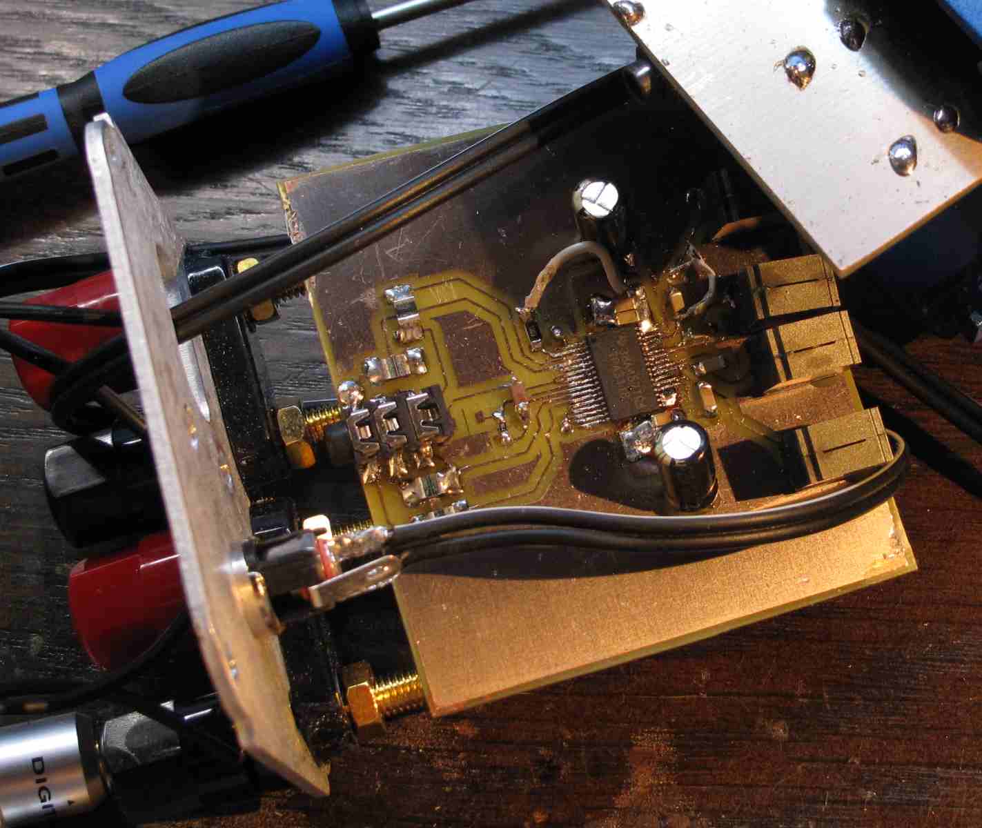
This device does indeed sound very nice and in my implementation I added an output filter using ICE components output inductors and poly caps that are soldered to the reverse side of the board.
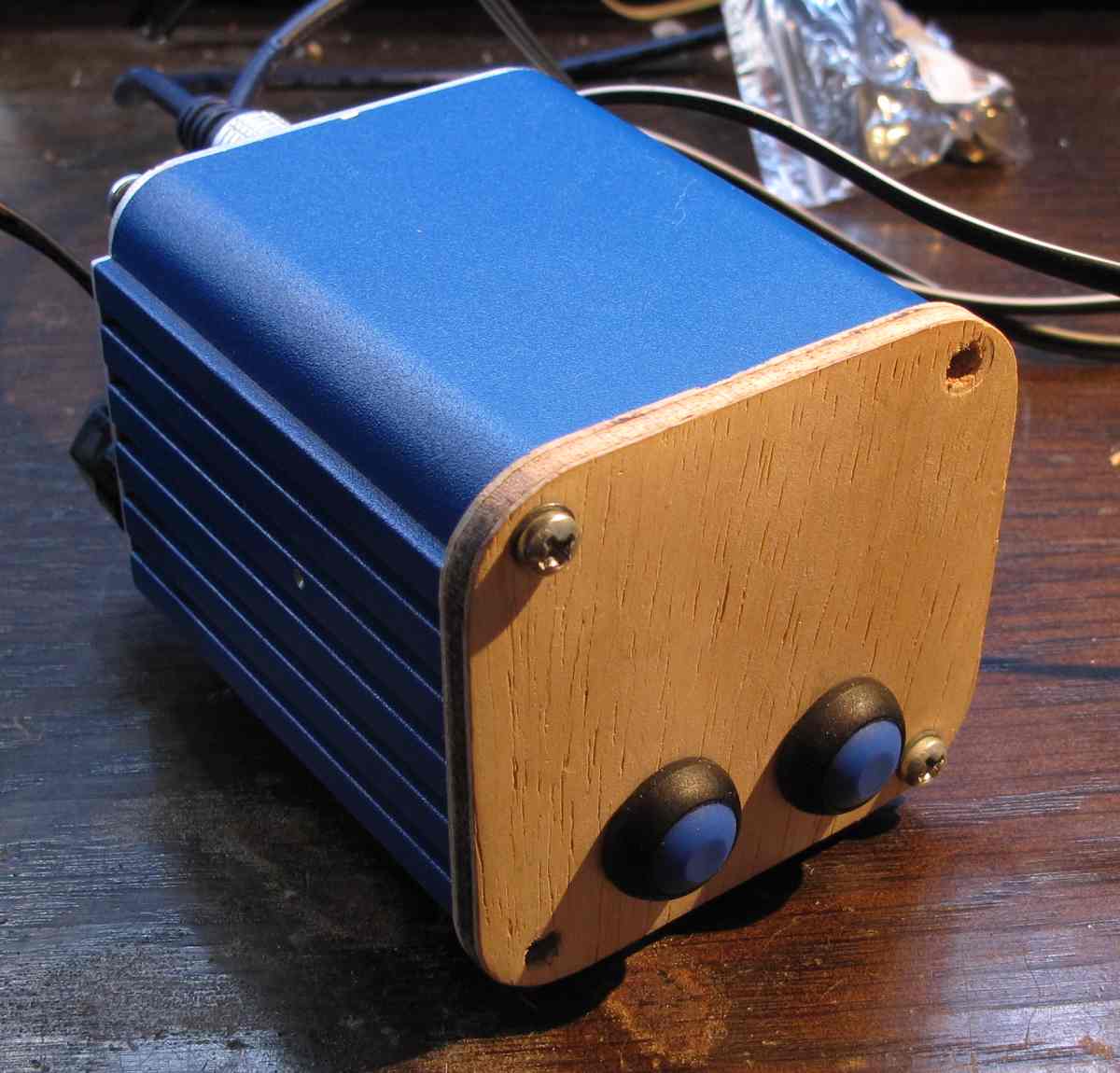
Both PCBs slide snugly into this natty little aluminium box that my Dad gave me years ago from a piece of equipment they were otherwise going to throw out at his work. The box finally now has a use 🙂.

Next up are the distortion measurements. The first measurement was done at 2.8VRMS. As you can see these are really rather clean with the aforementioned 1% distortion in the 3rd and 5th harmonics being banished to the land of blue smoke. For the price I paid, the Infinity tweeters are certainly a bargain and perform very well indeed. As you see though there are peaks in the 3rd 4th and 5th harmonics created by the dome resonating just above 20k.
And next up is the same but this time done at a much lower listening level, more representative of how loud I listen to them.
Finally we have a couple of pictures of the right one in place (sorry for the pictures being quite dark). The left one refused to co-operate by threatening to fall off the wall. Damned old crumbly walls.
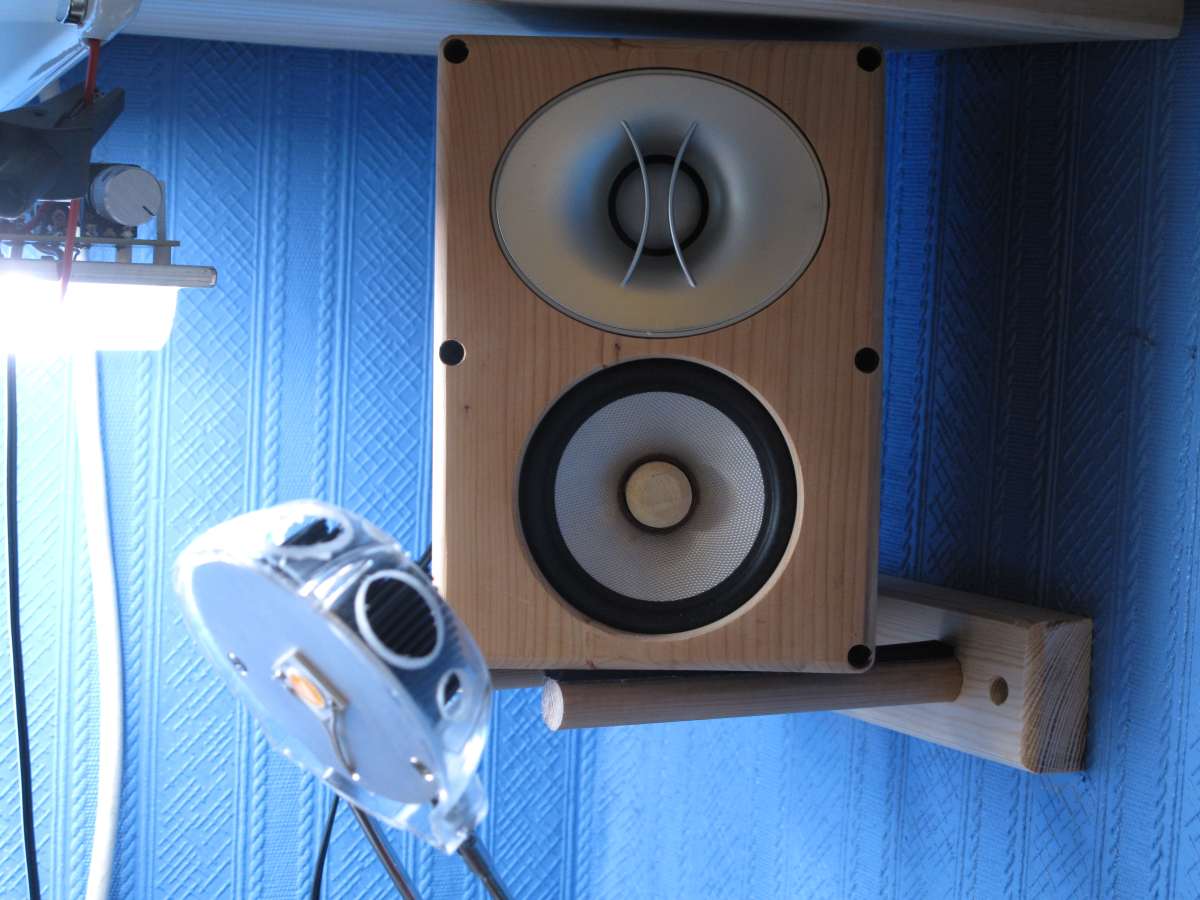
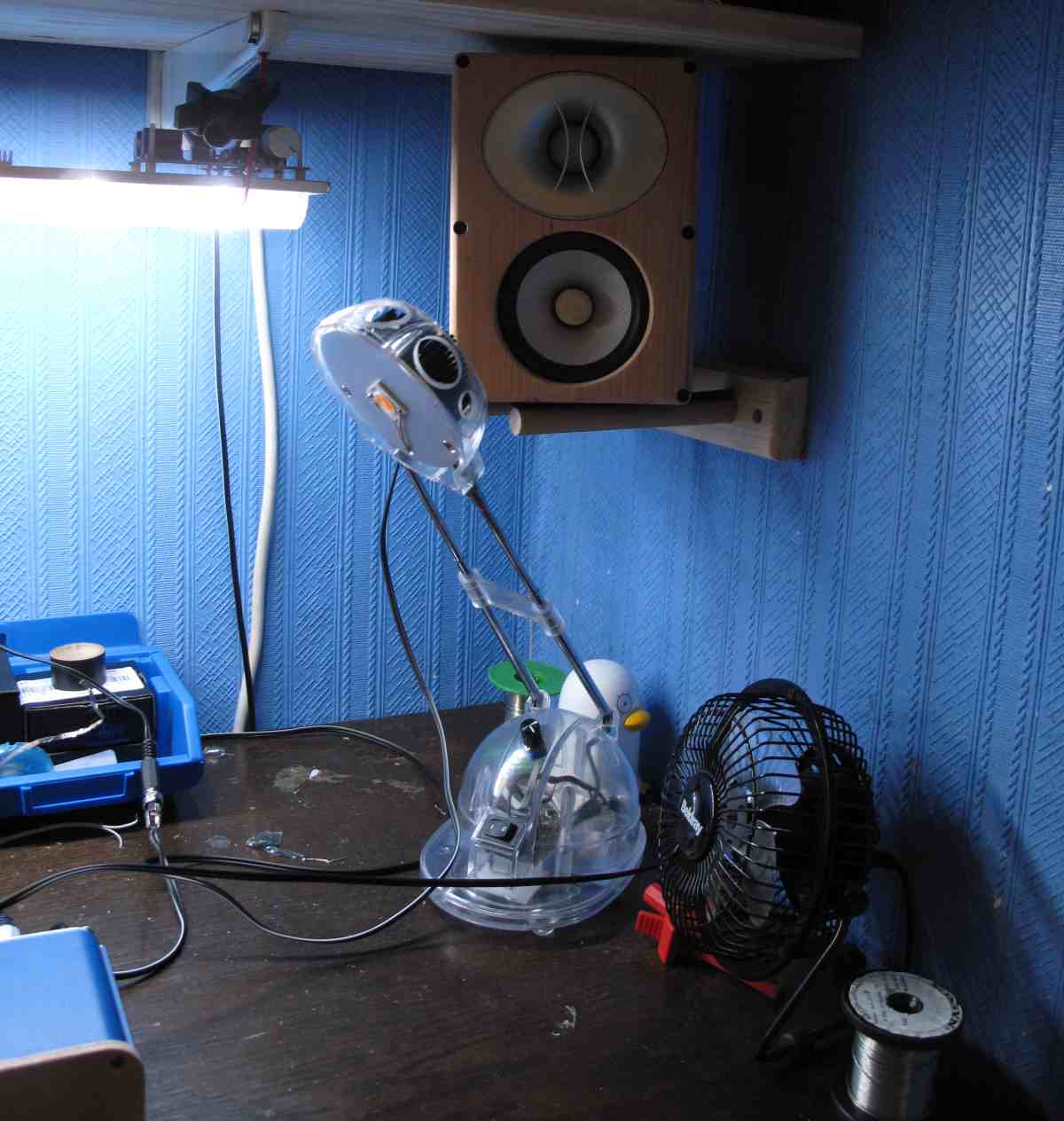
So how do they sound? Very good. Unfortunately I have hyperacusis and this make my ears very sensitive and can make listening to music on some systems extremely unpleasant. Luckily these are very easy to listen, extremely cohesive (most likely due to the close C2C spacing) and very smooth. I can listen to them all day without too much of a problem. In case you are wondering, even in the close proximity to the walls, I still ended up using around 4dB of BSC. 6dB was overkill, but it surprised me, as I thought they'd need close to 0dB compensation. I have also found that wave-guide loaded tweeters always fair better with how they trigger my hyperacusis and these Infinity's are certainly no exception, it wouldn't surprise me if they were also helping to reduce the effects of any reflections from the nearby surfaces too.
One thing that amazes me is how much bass they actually produce. Now I know that the LT really lifts the low end and that their max SPL capabilities are quite limited, but what is there is rather surprising given their size.
😎
Not so bad any more. One thing to note here is that the Infinity tweeter does roll off before it hits 20k, but this is mainly because it has a severe breakup just beyond 20k. The dip, before the resonance occurs, being pretty common place in some stiff coned drivers. This also shows up as distortion amplification in the HD products further down in the tweeters passband.
The final part of the system is the amplification, which is provided by another TI part, the TAS3118, the small brother of the TAS3116 that has it's own ridiculously long thread over in the class D forums.
This device does indeed sound very nice and in my implementation I added an output filter using ICE components output inductors and poly caps that are soldered to the reverse side of the board.
Both PCBs slide snugly into this natty little aluminium box that my Dad gave me years ago from a piece of equipment they were otherwise going to throw out at his work. The box finally now has a use 🙂.
Next up are the distortion measurements. The first measurement was done at 2.8VRMS. As you can see these are really rather clean with the aforementioned 1% distortion in the 3rd and 5th harmonics being banished to the land of blue smoke. For the price I paid, the Infinity tweeters are certainly a bargain and perform very well indeed. As you see though there are peaks in the 3rd 4th and 5th harmonics created by the dome resonating just above 20k.
And next up is the same but this time done at a much lower listening level, more representative of how loud I listen to them.
Finally we have a couple of pictures of the right one in place (sorry for the pictures being quite dark). The left one refused to co-operate by threatening to fall off the wall. Damned old crumbly walls.
So how do they sound? Very good. Unfortunately I have hyperacusis and this make my ears very sensitive and can make listening to music on some systems extremely unpleasant. Luckily these are very easy to listen, extremely cohesive (most likely due to the close C2C spacing) and very smooth. I can listen to them all day without too much of a problem. In case you are wondering, even in the close proximity to the walls, I still ended up using around 4dB of BSC. 6dB was overkill, but it surprised me, as I thought they'd need close to 0dB compensation. I have also found that wave-guide loaded tweeters always fair better with how they trigger my hyperacusis and these Infinity's are certainly no exception, it wouldn't surprise me if they were also helping to reduce the effects of any reflections from the nearby surfaces too.
One thing that amazes me is how much bass they actually produce. Now I know that the LT really lifts the low end and that their max SPL capabilities are quite limited, but what is there is rather surprising given their size.
😎
Attachments


I'd say a rather nice balance, everything considered 🙂
Enclosures reminded me of my old Minimus 11 toe crushers.
Why the increase in 3rd and 5th at 5kHz at lower levels, amplifier?
Enclosures reminded me of my old Minimus 11 toe crushers.
Why the increase in 3rd and 5th at 5kHz at lower levels, amplifier?
Thanks 🙂
The higher orders appear to increase because the signal to noise ratio starts to decline and increasing the drive level causes the fundamental to increase at a greater rate than the distortion products. The third actually decreases in some areas and increases in others. You often see this kind of thing happening, where a driver reaches a certain level of base linearity and decreasing the drive level further doesn't improve things by much, or as much as you'd expect. It's inherent non linearity wont actually go much lower.
You can help to improve the SnR issue by moving the mic closer to the loudspeakers, but with a multiway system you need to keep the mic a certain distance away to allow the drivers to sum correctly.
The rise in third in the last couple of octaves is entirely related to the Infinity tweeter as the TG didn't show this on its own. Why it goes up by such a large ammount is a bit of a mystery. This could be related to the ferrofluid in the gap though. These tweeters were never built to be particularly expensive units and at the lower drive level they really aren't being driven hard at all. It's possible that at lower drive levels maybe the viscosity of the ferrofluid actually effects things. The impedance isn't posted, but the raw impedance of the Inifinty is very flat, even at resonance, so clearly the fluid is quite thick to dampen it down in such an extreme way.
- Status
- Not open for further replies.