Hi all,
I'm going to build a fullrange TL. Since it's hard for beginner like me to use MJK TL MathCad directly, I would like to ask some basic question to guide me first.
1. Which is better, tune TL box slightly lower or higher then driver fs?
2. Which is better, tappered, straight or expanded TL?
3. Which is better, making TL length slightly shorter or longer?
4. Which is better, TL opening at the same side with driver or opposite (at the back)?
5. Which is better, TL opening close to driver or farther?
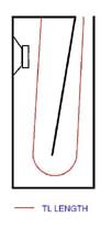
6. Is it correct to measure TL length as my dwg below (the red line)?
Thank you in advance for your help.
I'm going to build a fullrange TL. Since it's hard for beginner like me to use MJK TL MathCad directly, I would like to ask some basic question to guide me first.
1. Which is better, tune TL box slightly lower or higher then driver fs?
2. Which is better, tappered, straight or expanded TL?
3. Which is better, making TL length slightly shorter or longer?
4. Which is better, TL opening at the same side with driver or opposite (at the back)?
5. Which is better, TL opening close to driver or farther?
6. Is it correct to measure TL length as my dwg below (the red line)?
Thank you in advance for your help.
Attachments
Hi Christophorus,
1. Tune the TL at fs or higher. Perhaps as high as 1.5*fs
2. Don't do expanded. Tapering allows you to reduce the tuning of the line compared to a striaght line. If you taper from 4 * driver Sd to 0.5 * driver Sd, you can figure that the line will be tuned to about 65% of the equivalent straight line frequency. For example, if you take a 72" line: 13500 in/s (speed of sound) / 4 / 72 gives you about 47 Hz. If you taper 8:1, you'll reduce it by about 35%.
3. Shorter gives you higher tuning and more amplitude, but doesn't attenuate the higher harmonics as much with the same stuffing density. Of course you can increase the density to offset this.
4. Open on the back near the bottom if possible to make use of the floor boundary for additional gain.
5. Farther is fine. If you open on the back near the floor, you get a gain boost and also you allow the higher harmonics to radiate into the reverberant field rather than direct. They will be less noticable...
6. Yup.
Brendon
6.
Hi Christophorus,
"I'm going to build a fullrange TL. Since it's hard for beginner like me to use MJK TL MathCad directly, I would like to ask some basic question to guide me first."
If you are having trouble with the MathCad worksheets, you might try the alignment tables to get a design concept. Then you can decide if you want to put this design into the worksheets and see if it could be optimized.
"1. Which is better, tune TL box slightly lower or higher then driver fs?"
Depends on the driver Qts, I don't believe that there is a hard rule one way or other. I tend to tune a little below fs to try and extend the response just a bit lower. I like drivers with a Qts between 0.3 and 0.5 best for a classic TL design. If the Qts is higher then 0.5 then the bass will be a little less controlled and may ring.
"2. Which is better, tappered, straight or expanded TL?"
Any of the three can be optimized to give almost the same SPL response. For the smallest enclosure I would go with a tapered TL, I think that this is the safest design approach if you use the alignment tables.
"3. Which is better, making TL length slightly shorter or longer?"
Making it the correct length with the end correction accounted for is the best, again the alignment tables will help set the correct length. There is a lot of flexibility in a tapered TL and small mistakes will not be a disaster.
"4. Which is better, TL opening at the same side with driver or opposite (at the back)?"
Doesn't matter.
"5. Which is better, TL opening close to driver or farther?"
Doesn't matter.
"6. Is it correct to measure TL length as my dwg below (the red line)?"
Yes, your sketch is correct and the length is measured down the middle of the line.
Hope that helps,
Hi Brendon and MJK,
Thanks for your quick answer, basically I get what I need to know,
however I still have a few unclear thing about it.
1. If I tune the TL below fs, how far it can go before something terrible happen?
any chart for this or just use MathCad to see what happen?
2. Brendon:"Open on the back near the bottom if possible to make use of the floor boundary for additional gain." is there any unwanted effect can happen for this setup?
3. is there any change in sound quality with placement of TL opening (far/near driver or at the same side/opposite driver) like if we seperate mid & tweeter to far? Or I can place it anywhere?
4. How big total volume of TL box compared with Vas of the driver as a rule of thumb?
Thankyou.
Chris.
Hi again, Christophorus,
1. I think Martin's sheet could probably give an indication as such, but what I'd estimate is that you'll see the amplitude of the pipe drop dramatically as you go below fs. The driver can't support the resonance below.
2. You can get a result that's a 'boomy'. The solution, though, is additional stuffing to dampen the output to taste. You'll, of course, find that bass is very room dependant regardless of the speaker in question. Within a single room, different setups will also have different results. I see this as a positive since you have more freedom to tune to your taste.
For instance, I've tried a very short line of about 1.5 * fs, emptying directly down to the floor. The height of speaker above the floor influences the amount of gain. 1" above the floor gives more apparent amplitude than the same length line with a 3" gap between the floor and the terminus. Stuff unchanged.
3. No change, not like a tweet to mid x-over. But I would recommend against having the terminus on the front facing the listener. Top back like you showed earlier would be fine. Having it at the floor just gives you a bit more freedom to tweak / adjust to taste.
4. I think Martin's tables would be a good judge for this, but in my mind, I normally look for drivers in the Qts range Martin mentioned. Further, I mentally choose 4 Sd as a start for the line and go from there, depending on what I'm doing. For instance, a short line, heavily sfuffed with few bends (or none) is good if you're going to bi-amp with a separate sub. Why worry about getting low end support from resonance if you have a sub? I see the benefit in this case to be the open-ness of the TL's output, not the extension benefits.
If you start at 4 Sd and then taper to 0.5 Sd, you'll have as optimized a line as you can do in terms of total volume. You could reduce the starting area, but then you lose the benefit of some of the taper.
Hope it helps,
Brendon
Hi MJK,
from your Mathcad, how do I know TL freq. resonance (Fr) of my calculation? (I use TL offset driver.mcb for my tapered TL calc.)
Is there any direct corelation between TL length and TL Fr?
I look mostly at freq. response graph (6th graph from top) for calculation, what else (graphs) should I pay attention to get the best result?
Thankyou,
Chris.
Hi MJK,
Now I try using your TL section.mcd, but apparently I'm stuck!
My design is folded tapered TL, optimized with your TL offset driver.mcd and then I feed thee result into TL section.mcd and I got stuck at this section:
n_closed=4
n_open=4
what does it mean?
Since I use folded tapered TL (as attch. dwg in my first post), what should I put into Lc0 to Lc4 and Lo0 to Lo9?
Would you mind giving me a brief explanation for this whole section?
Thankyou,
Chris.
Hi Chris,
If you look at the TL Application Note and the worksheet TL_Sections I'll try and give a brief explanation.
n_closed - the number of sections used to model the closed end
n_open - the number of sections used to model the open end
These are basically the number of elements defined below where each line represents one element (note the counter starts at 0). So for n_closed = 4 requires 5 lines of input to model the closed end of the TL, the maximum subscript number should equal n_closed. For n_open = 9 means that 10 sections are used to model the open end of the TL and again the maximum subscript number should equal n_open. Looking at the application note, the closed end is not shown in detail but the open end shows 10 sections defined by the dashed lines. The dotted line traces the path and the dashed lines show the initial and final areas of each section. You should understand everything in this worksheet and Application note before you attempt to modify TL_Sections.
You can use any number of sections that you want as long as n_closed and n_open are greater than 1 (two lines of input) If you look at the back loaded horn worksheets you can see another example ot TL_Sections.
You can input step changes in area by setting the final area of a section not equal to the initial area of the next section. You can accurately model corners but at low frequencies this is really not critical or needed.
If you really are struggling understanding TL-Sections, I recommend sticking with the other preformatted worksheets. TL_Sections will solve any problem that you input, even if it is not the correct model for your enclosure.
Hope that helps,
hi MJK,
thanks for your brief explanation, I missed your TL app. notes, then I downloaded it and combine with your post above, now your TL section.mcd more easy to understand!
However, I still have a question if you don't mind.
Why n_closed and n_open number not equal with total of sections? (always -1)
That question came from closed end section from your TL app. notes:
On the closed end section, you divided it into 5 sections, right?
Actually, that 5 sections have the same initial and final area, so why you divided it into 5 sections?
Because it is a rectangular form, can we make it just as 1 section with section length=6"? (measured from center-line of the driver to the top, right?), so it becomes:
n_closed=1
Section length...Initial Area... Final Area
Lc0=6in...........Sc0,0=3.Sd...Sc0,1=3.Sd
so: n_closed equal with total of section, or I must add 1 line more? -->
Lc1=6in...........Sc1,0=3.Sd...Sc1,1=3.Sd
I need one step more to understand it, with your great help, surely I can make it.
best regards,
Chris.
Hi Chris,
If I remember correctly, you need n_open and n_closed to be >= 1 for the algorithm that calculates the acoustic impedance to work correctly. This has nothing to do with the geometry or the physics of the problem but is an odd feature of one of the math functions I used in MathCad. It is also a feature within MathCad, unless you redefine the defaults which would then mess up other calculations, that all counters start at 0. So when n_closed = 1, the internal looping covers n_closed=0 and then 1.
For the example we are looking at, I could have set n_closed equal to 2, 4, 6, or 100. It does not matter the answer will be the same. The only thing that will change is the amount of time to enter the input and than calculate the result. I just happened to select this number of sections thinking that it would cover almost any changing geometry, if you have a tapered or expanding pipe with the driver located well along the pipe it is more accurate to have the additional sections in n_closed. If you change n_closed you end up having to add or delete rows of input which can be tricky. I set the worksheet up to try and make it easy for people to use with a minimum amount of editting.
You are free to change the number of sections (n_closed or n_open) to anything you would like but please be careful. The editting can be tricky and unless you are really familiar with MathCad and understand how it defines subscripts and array element numbering it can get really confusing. You open yourself up for error messages and a worksheet that does not calculate. If you are an experienced MathCad user, then it should be easy to adjust this worksheet.
Hi again Chris,
Thought a little more about your questions and thought I would let you in on another one of my hidden secrets. If you look at the following worksheets
TL_Sections
ML_TQWT
TL_Offset_Driver
BLH
DBR
you will find that they are all the same worksheet. I used TL_Sections to create them by hard coding in the detailed inputs based on minimal information on the first page. So you can look at any of thses as additional examples of TL_Sections and as different options you might have for describing your enclosure designs.
TML line lenght?
Hi!
I am a bit confused about the TML line lenght calculating methode, because most of time I read that the builders use the Classic Transmission Line Rules of Thumb :
"make the line length ~ 1/4 the wavelength of Fs (1/4 wavelength will be the F3 point)
taper the line from 1.25 - 2 Sd down to Sd at the port
after building it, stuff the line -- increasing or decreasing the stuffing till it sounds right...... "
,but I saw some design in the German Hobby HiFi magazine, for example the Lancetta TML speaker, where they made the line lenght much more longer and tuned much lower than the Fs of the driver.In this way they got the driver impedance plot almost in the same frequency as it would have been in an infinite baffle and also gained a lot of bass!
The driver is the Tang Band W3-871S, Fs=110Hz, Sd= 32cm2, Vd= 1.66L, Qt =0.591. The Box is straight line 115cm, with 3.75-3.75 Sd on the ends. It is tuned to 74Hz and not to 110Hz.
When I modeled boxes with the Classic Rules of Thumb I got every time very weak bass gain and the impedance plot was far from the infinite baffle's.
Martin J. King wrote also same similar: He has tried a number of alignment frequencies and found that the best system response was achieved by positioning the acoustic impedance plot’s first peak at approximately 34 Hz, when the driver free air Fs was 34 Hz too.
So, my question is : which way is better?
- to make the line length ~ 1/4 the wavelength of the drivers Fs or..
-make the line length so long then I get the acoustic impedance plot’s first peak at approximately similar like if it would be in the infinite baffle?
Tyimo
Hi Tyimo,
There are many different combinations of driver T/S properties and enclosure geometries that will work for a TL. To simplify the problem I made a few assumptions (fd = fl for example) that lead to just one set of alignment tables. Different assumptions would have resulted in different alignment tables. It is similar to BR alignment tables where you can use a Butterworth, a Chebyshev, or one of the other alignments found in the LSDC with your driver of choice. Each has its own set of strengths and weaknesses. My tables are definitely not the only possibility, but just one of many.
This is what I found, the Classic Rules of Thumb are not very good. Also, I would not recommend trying to obtain an impedance plot like an infinite baffle, most of the designs I have built or seen on the web tend to have impedance plots more like a damped BR enclosures. Typically these impedance curves are double humped with the first peak significantly damped by the fiber. This type of design has output from the open end of the TL augmenting the driver's falling bass response. But agina, this is only one option.
Sounds too good to be true, have you modeled this design to see if the claims are accurate.
There are several incorrect points in the above guidelines. If you make the enclosure length equal to the quarter wavelength of the tuning frequency, then typically your length is calculated as follows
L = c / (4 x f)
which is correct for a straight constant area TL. But then adding the taper tunes the line lower then this frequency. A tapered TL will have a lower quarter wavelength frequency then the calculations above would yield. An expanding TL (or TQWT) would have a higher quarter wavelength frequency then the results of this type of calculation. This is probably the most common mistake made by DIY TL designers. If you look at Table 1 in my alignment tables article you will see the relationship between length, taper, and frequency for a wide variety of TL geometries.
Bottom line, don't look for a TL alignment that is absolutely the best. There will always be some trade-offs and compromises. You as the designer need to set goals for your TL system and design to meet those goals. Your goals may not be the same as my goals. There is no right or wrong answer, nothing is perfect. Don't end up in analysis paralysis. Design something, build it, listen to it, you will learn a lot and the next one will be even better. Have fun, who cares what anybody else says is best ....... including me.
Hope that helps,
Martin J. King wrote also same similar: He has tried a number of alignment frequencies and found that the best system response was achieved by positioning the acoustic impedance plot’s first peak at approximately 34 Hz, when the driver free air Fs was 34 Hz too.
There are many different combinations of driver T/S properties and enclosure geometries that will work for a TL. To simplify the problem I made a few assumptions (fd = fl for example) that lead to just one set of alignment tables. Different assumptions would have resulted in different alignment tables. It is similar to BR alignment tables where you can use a Butterworth, a Chebyshev, or one of the other alignments found in the LSDC with your driver of choice. Each has its own set of strengths and weaknesses. My tables are definitely not the only possibility, but just one of many.
When I modeled boxes with the Classic Rules of Thumb I got every time very weak bass gain and the impedance plot was far from the infinite baffle's.
This is what I found, the Classic Rules of Thumb are not very good. Also, I would not recommend trying to obtain an impedance plot like an infinite baffle, most of the designs I have built or seen on the web tend to have impedance plots more like a damped BR enclosures. Typically these impedance curves are double humped with the first peak significantly damped by the fiber. This type of design has output from the open end of the TL augmenting the driver's falling bass response. But agina, this is only one option.
but I saw some design in the German Hobby HiFi magazine, for example the Lancetta TML speaker, where they made the line lenght much more longer and tuned much lower than the Fs of the driver.In this way they got the driver impedance plot almost in the same frequency as it would have been in an infinite baffle and also gained a lot of bass!
Sounds too good to be true, have you modeled this design to see if the claims are accurate.
"make the line length ~ 1/4 the wavelength of Fs (1/4 wavelength will be the F3 point)
taper the line from 1.25 - 2 Sd down to Sd at the port
after building it, stuff the line -- increasing or decreasing the stuffing till it sounds right...... "
There are several incorrect points in the above guidelines. If you make the enclosure length equal to the quarter wavelength of the tuning frequency, then typically your length is calculated as follows
L = c / (4 x f)
which is correct for a straight constant area TL. But then adding the taper tunes the line lower then this frequency. A tapered TL will have a lower quarter wavelength frequency then the calculations above would yield. An expanding TL (or TQWT) would have a higher quarter wavelength frequency then the results of this type of calculation. This is probably the most common mistake made by DIY TL designers. If you look at Table 1 in my alignment tables article you will see the relationship between length, taper, and frequency for a wide variety of TL geometries.
Bottom line, don't look for a TL alignment that is absolutely the best. There will always be some trade-offs and compromises. You as the designer need to set goals for your TL system and design to meet those goals. Your goals may not be the same as my goals. There is no right or wrong answer, nothing is perfect. Don't end up in analysis paralysis. Design something, build it, listen to it, you will learn a lot and the next one will be even better. Have fun, who cares what anybody else says is best ....... including me.
Hope that helps,
Hey everyone,
I'm new to this thread, But I am working on designing a TL subwoofer and figured I'd ask someone experienced for help. I was wondering if a half wavelength pipe would have similar response to a quarter wavelength pipe? I figured it might be close above the quarter wavelength frequency due to the pipes sharing the same harmonic resonances. The reason I asked was because I wish to make my first TL for an Adire Tumult I have. The Fs of the driver is at 19hz and I'd have no problem building a quarter wavelenght pipe for it, but I am unsure how well the sub will extend below 20hz. I was thinking I could instead use a quarter wave pipe at 10hz and it might give me good infrasonic capability while still giving the same audible response. I have no idea if my thinking here is flawed or could I possibly be right?
I'm new to this thread, But I am working on designing a TL subwoofer and figured I'd ask someone experienced for help. I was wondering if a half wavelength pipe would have similar response to a quarter wavelength pipe? I figured it might be close above the quarter wavelength frequency due to the pipes sharing the same harmonic resonances. The reason I asked was because I wish to make my first TL for an Adire Tumult I have. The Fs of the driver is at 19hz and I'd have no problem building a quarter wavelenght pipe for it, but I am unsure how well the sub will extend below 20hz. I was thinking I could instead use a quarter wave pipe at 10hz and it might give me good infrasonic capability while still giving the same audible response. I have no idea if my thinking here is flawed or could I possibly be right?
Hi Martin!
Thanks a lot for your answer!
I was suspecting too, what you wrote, but now it is more clear to me.
Yes, I modeled the Lancetta, and I got pritty good reasult, of course they used some Helmholz resonator chamber for the smooth frequency response.
I read somewhere that the most important part, what cause the famous TML sound character is the nice flat impedance, because the amps can work very well with it. So, I am looking for a design what has as low and smooth imledance plot as possible and I try to avoid designs with "Bass reflex kind" impedance. The problem is, that I can not find an optimal solution for my driver with I coud gain much bass and also low and smooth impedance.... The best frequency and bass gain reasult I got with MLTQWT, but I am affraid it would sound more like a BR box. :-((
With straight and expanded line I got some bass gain and low impedance, but the frequency response was full with pikes. I don't konw how much I have to care about these pikes in the reality?
Here are my driver data:
Sd=132cm2
Fs=59Hz
Qts=0.36
Vas=20.63L
Rc=6.2Ohm
BL=6.83 Vs/m
Mme=8.61gr
Qe=0.43
Qm=2.51
92dB
May be You or somebody could sugest some solutions?
Tyimo
P.S.: I would like to reach ca. 40 Hz on F3 without room gain, if it is possible?!?
Hi Tyimo,
I think that a flat impedance curve and significant bass extension from the open end of the TL are mutually exclusive goals. As you add stuffing to a TL the first of the double impedance peaks is significantly attenuated and at the same time the bass energy generated by the quarter wavelength standing wave is also attenuated. As even more stuffing is added the impedance curve is flattened and the bass output is heavily damped. The system output starts to apporach the output for the driver in an infinite baffle.
Personally, I try and use a minimal amount of stuffing. I want the bass output from the fundamental quarter wavelength standing wave to help the driver produce bass. I use geometry (such as mass loading or tapers) to control the ripple and only use light stuffing densities. That is my approach and it seems to produce deep well controlled bass output, it is definitely not a typical underdaped BR sound.
I read somewhere that the most important part, what cause the famous TML sound character is the nice flat impedance, because the amps can work very well with it. So, I am looking for a design what has as low and smooth imledance plot as possible and I try to avoid designs with "Bass reflex kind" impedance. The problem is, that I can not find an optimal solution for my driver with I coud gain much bass and also low and smooth impedance.... The best frequency and bass gain reasult I got with MLTQWT, but I am affraid it would sound more like a BR box. :-((
I think that a flat impedance curve and significant bass extension from the open end of the TL are mutually exclusive goals. As you add stuffing to a TL the first of the double impedance peaks is significantly attenuated and at the same time the bass energy generated by the quarter wavelength standing wave is also attenuated. As even more stuffing is added the impedance curve is flattened and the bass output is heavily damped. The system output starts to apporach the output for the driver in an infinite baffle.
Personally, I try and use a minimal amount of stuffing. I want the bass output from the fundamental quarter wavelength standing wave to help the driver produce bass. I use geometry (such as mass loading or tapers) to control the ripple and only use light stuffing densities. That is my approach and it seems to produce deep well controlled bass output, it is definitely not a typical underdaped BR sound.
Hi Martin!
Thanks!
3 more questions:
-When I modeled some existing design I got very uneven frequency response, full with peakes and I don't know how much need I to care about it? I mean: people say that the loudspeaker sounds very good in the reality in spite of that the box hasn't got the totaly smooth frequency plot. I have at home only one reference TML speaker and it is sounding excellent and it has also some "bad, speaky " (+/- 10dB) SPL in the simulation.....
-If I put the speaker in a calculated box volume the free air resonance of the driver will change, usually get lower. Could it be this the reason, that some designer calculating lower tuning frequency as the classical methode says?
You wrote: " The driver resonant frequency of approximately 34 Hz reported in Table 1, dropped to 22 Hz when the driver was mounted in the test transmission line...."
Jon Risch wrote something, but I don't understand 100%:
"The line length should be 1/4 wavelength tuned to the resonant frequency of the chosen speaker IN THE BOX VOLUME CREATED BY THE TOTAL T-LINE CROSS SECTIONAL AREA TIMES LENGTH, and as if the box were a closed box..."
-Could you suggest something for my aerlier posted driver?
Thanks and greets:
Tyimo
- Status
- This old topic is closed. If you want to reopen this topic, contact a moderator using the "Report Post" button.
- Home
- Loudspeakers
- Multi-Way
- Tl Basic Design Question.