In a few posts on this forum, I'd argued that narrow angle horns had higher output on axis but rougher response, while wide angle horns had less output on axis but smoother response.
Art had argued that this is not the case.*
So I decided to do some measurements, to determine if my statement was incorrect.


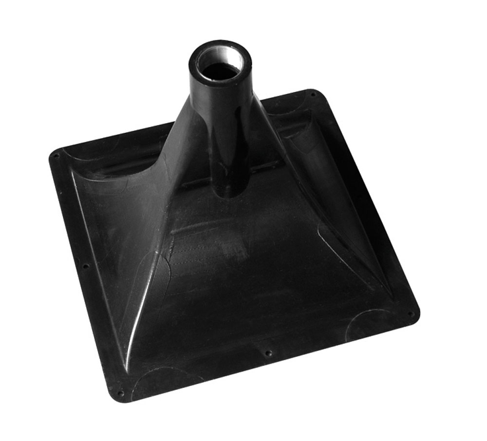
The horn at the top is a 90x90 round waveguide sold by QSC.
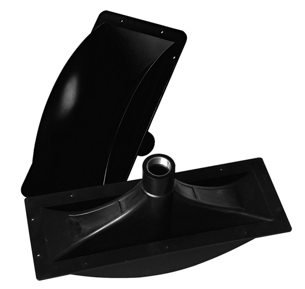
The second horn is a 90x60 rectangular waveguide sold by QSC.
The last horn is a car audio horn with a narrow vertical angle, about 20 degrees, and a wider horizontal angle, about 40ish. (Hard to say exactly because it's a horn not a waveguide. The shape looks similar to an exponential horn.)
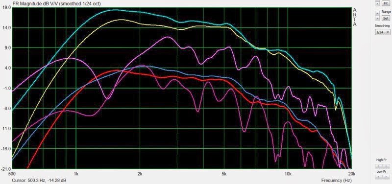
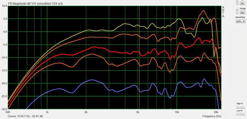
Here's the measurement of all three, on the same graph.
The yellow, cyan, and violets curves are the on axis response of the round, rectangular, and car audio horn.
The red, blue, and purple curves are the 45 degree off axis response of the round, rectangular, and car audio horn.
Based on these measurements, I'd say the differences between the 90x90 and the 90x60 degree horns from QSC are small. If anything, the narrower horn is a little bit smoother. OTOH, the frequency response of the car audio horn is noticeably rough.
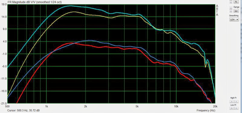
In this measurement, I've omitted the car audio horn to highlight the response differences of the two QSC waveguides. Above 5khz, the response of the two waveguides is within +/- 3dB of each other. Below 5khz the larger waveguide has more output, but they're both very smooth. I believe the larger waveguide has more output below 5khz simply because the smaller waveguide has a large integrated roundover in the waveguide.

In this illustration I've overlaid a 90 degree cone on the round QSC waveguide; I've done this to illustrate how a substantial amount of the waveguide's dimensions are the termination.
Based on these measurements, I believe that Art is correct. Narrow angle waveguides aren't inherently more ragged than wide angle waveguides. The majority of my experience with horns and waveguides is in the arena of car audio, and I'd long assumed that the ragged response of car audio horns was something that's shared with ALL narrow angle horns. This is not the case apparently.
Hopefully I don't get myself in MORE hot water with a hypothesis of mine, but my hypothesis about the car audio horn is that the frequency response is ragged due to high order modes. If you look at the impulse response of the car audio horn, there's a huuuuuuge tail of reflected energy. My theory is that this is due to the 90 degree bend that the compression driver fires into.
*http://www.diyaudio.com/forums/multi-way/217298-square-pegs-61.html#post3743806
Art had argued that this is not the case.*
So I decided to do some measurements, to determine if my statement was incorrect.
The horn at the top is a 90x90 round waveguide sold by QSC.
The second horn is a 90x60 rectangular waveguide sold by QSC.
The last horn is a car audio horn with a narrow vertical angle, about 20 degrees, and a wider horizontal angle, about 40ish. (Hard to say exactly because it's a horn not a waveguide. The shape looks similar to an exponential horn.)
Here's the measurement of all three, on the same graph.
The yellow, cyan, and violets curves are the on axis response of the round, rectangular, and car audio horn.
The red, blue, and purple curves are the 45 degree off axis response of the round, rectangular, and car audio horn.
Based on these measurements, I'd say the differences between the 90x90 and the 90x60 degree horns from QSC are small. If anything, the narrower horn is a little bit smoother. OTOH, the frequency response of the car audio horn is noticeably rough.
In this measurement, I've omitted the car audio horn to highlight the response differences of the two QSC waveguides. Above 5khz, the response of the two waveguides is within +/- 3dB of each other. Below 5khz the larger waveguide has more output, but they're both very smooth. I believe the larger waveguide has more output below 5khz simply because the smaller waveguide has a large integrated roundover in the waveguide.
In this illustration I've overlaid a 90 degree cone on the round QSC waveguide; I've done this to illustrate how a substantial amount of the waveguide's dimensions are the termination.
Based on these measurements, I believe that Art is correct. Narrow angle waveguides aren't inherently more ragged than wide angle waveguides. The majority of my experience with horns and waveguides is in the arena of car audio, and I'd long assumed that the ragged response of car audio horns was something that's shared with ALL narrow angle horns. This is not the case apparently.
Hopefully I don't get myself in MORE hot water with a hypothesis of mine, but my hypothesis about the car audio horn is that the frequency response is ragged due to high order modes. If you look at the impulse response of the car audio horn, there's a huuuuuuge tail of reflected energy. My theory is that this is due to the 90 degree bend that the compression driver fires into.
*http://www.diyaudio.com/forums/multi-way/217298-square-pegs-61.html#post3743806
Last edited:

Some notes on the measurements:
1) All measurements use the same compression driver, a Celestion CDX1-1425
2) I didn't take pictures of the horns today; the pictures in the first post are old pictures that I took. So even though there's a BMS 4540ND in one pic, I didn't use that.
3) The 45 degree off axis curves have been lowered by 10dB to make it easier to see the data on the same graph
4) I had the mic in a fixed location to insure that the curves were accurate
5) I rotated the horns and waveguides in place to insure accuracy. (Basically I noticed that the curves would vary by a dB or two if I wasn't careful, so I paid special attention to the location of both the mic and the horns.)

Here's a couple more examples. The yellow curve is a Pyle PH714, a 90x40 degree horn that measures 16.5" x 6.25". The cyan curve is a Pyle PH12S, a "90x40" degree horn that measures 11.6" x 11.6". I put "90x40" in quotes because the PH12S is nearly twice as tall as the PH714 and it's vertical coverage is clearly larger.
The difference between the two curves isn't significant, except for a blip at 5.5khz and 15khz. The latter is likely due to a bit of a mismatch between the compression driver and the horn. (The Pyle horns leave a gap of about a millimeter between the compression driver and the horn, and the gap is worse with the PH714.)

The yellow curve is a Pyle PH714 on axis, the red curve is the same horn 45 degrees off axis. The cyan curve is a Pyle PH12s on axis, the dark blue is the same horn 45 degrees off axis.
IMHO the PH12S is a bit smoother than the PH714, but the QSC waveguides are smoother than both. That may be due to the compression driver, a mismatch between the horn and the compression driver, the geometry of the horn, all the above, or something else. The compression driver is a JBL 2408H-1.
Your premise is somewhat similar to the topic of the "Uniform Directivity" thread, except that I wasn't so much focused specifically on "wide versus narrow" as I was on a broader scope, the fact that some waveguide/horn features provide smoother response than others. If quality is desired, it isn't enough to chose a popular flare profile, set the tangential exit angle and "call it good."
I think most people expect the flare profile to have a great deal of influence on the response shape and directivity. And most consider mouth shape to set the polars at the lower end, and that the shape of the main body of the bell sets directivity higher up. But there are other details that are important, and so, as I sad earlier, I think it is not enough to choose a popular profile and wall angle and assume that this represents an optimized design. Measurements show me that attention to detail brings rewards in smoother response.
One trend I've seen appear in recent years is a sort of assumption that as long as a popular profile is chosen, then everything else will take care of itself. Ten years ago it was tractrix horns. This decade it seems to be OS, OSPS or OSEC. As a result, I see a lot of waveguide adopters resigned to using EQ to smooth response of their peaky horns. They build a device, and if it proves to have excessive ripple, instead of redesigning, they are satisfied just to equalize it flat.
This is a surprising trend, at least to me. I have always worked towards a goal of designing horns that provided smooth response without equalization. I'm not talking about mass-rolloff compensation, which is really equalization for the driver, not the horn. That's fine, a simple first-order slope. What I'm more concerned with are resonant waveguide/horns, devices with internal standing waves and/or other discontinuities that are manifested in the response curve.
So that was really the thrust of the "Uniform Directivity" thread, to look at the details of various waveguide/horn flares and the response and directivity that resulted from them. Even with the same basic horn profile and mouth size, one can see a wide variance in response, depending on wall angle, aspect ratio and mouth termination.
Last edited:
I would argue that that, everything else being equal, a wide angle horn should indeed have a smoother response. At least for an idealized conical/constant directivity horn.
Imagine an idealized conical horn of infinite length (and hence mouth area). If the source at the throat is infinitesimal in size and the walls are a perfect acoustic mirror, then narrow vs wide angle doesn't matter. They would tile space equally well.
But as soon as you give the driver a finite size or introduce any imperfections in the walls, the narrow horn would be the first to suffer. The response would deviate more rapidly from the idealized mathematical model. There is more interaction between the acoustic wave and horn walls if the horn is narrower.
And as soon as you make the horn finite in length the mismatch to free space is more pronounced for a narrower horn.
Whether this thought experiment translates to to an effective practical difference is another matter, I suppose.
I was looking at this response graph, and it seemed like a lot of the lumps in high frequency may be due to an atrocious step that exists in the throat of the Pyle horns.

The gap in the throat is huge; I was looking around the garage to find something that would smooth the transition. Tried using 1" PVC but it's a bit too big, because the outer diameter of PVC is 1.3". I found some spacers used with wire shelving, and due to their taper, they seemed to be a good place to start.

Here's that spacer IN the throat of the horn; despite being about 1.25", it actually fits! Yowza. That means there's a "step" at the throat that's about three tenths of an inch. That's ugly.

I popped off the bug screen and that makes it easier to see the step. See that silver ring? That should be hidden if the throat was a good match for the compression driver. The gap is so huge, for a second I thought the JBL might be a funky size like 7/8". But this isn't the case; the Pyle just doesn't match.
I stuck some clay in the throat, and did my best to smooth the transition from compression driver to horn. Here's the results of that. I used some EQ and a low pass on my MiniDSP to flatten out the response.
1) yellow is on-axis
2) orange is 15 degrees off axis
3) red is 30 degrees off axis
4) the lowest orange curve is 45 degrees off axis
5) The blue curve is the average of the first four curves.
The response curve isn't perfect, but it's improved, and I think the curve could be even better if I used something like Bondo instead of clay. (It's hard to get the clay perfectly smooth.)

Here's the vertical polars of the same horn. Blue is the average of 0,15,30 and 45. The verticals are a bit smoother than the horizontals, except for a nasty dip at 13,500hz. 13,500hz is one inch long, and I wonder if that dip is due to the parallel walls in the diffraction slot. You can see the dip in the on-axis of the horizontals, but it gets smaller when you get off axis. So it may be possible to use this horn in a speaker that's designed for listening off-axis. For instance, if you look at the 30 degree curves of the horizontal axis, they're smoother than the on-axis curve of both the horizontal and the vertical.
When designing a horn, I would strongly suggest modeling with Hornresp and then of course measuring for verification. Remember that some things are sort of counter-intuitive. An example would be waistbanding, which narrows the beam to an angle smaller than the wall angle. There are a few things like that which may initially bring surprise.
The matter of response smoothness versus beamwidth is another counter-intuitive example. You'll find that a larger coverage angle does not always result in smoother response.
The matter of response smoothness versus beamwidth is another counter-intuitive example. You'll find that a larger coverage angle does not always result in smoother response.
the usd horn is a bad design period. you ever took an impedance sweep of driver on that horn?
I'm always reluctant to say anything bad about USD because they are just such nice guys. True story:
I walk into USD about sixteen years ago. I'd read about Richard Clark's Grand National, and how he used horns. I figured I'd get in on this, and I was prepared to spend $600 on a set of USD horns.
So I'm talking to Eric, and he demos Harry Kimura's Acura, and I'm just floored. I'd *never* heard a car stereo that even came CLOSE to that. Dynamics, imaging, it just did things I'd never heard before. (At the time I had Dynaudio in my car, and it was very 'polite' sounding. I'm into EDM now and always, and the sound of horns was just what I was after.)
At this point, I want these horns badly, even more than when I walked through the door.
But here's where things take a turn:
During our conversation, I mentioned to Eric that I'd studied various papers on horns, and that I'd even built a few tractrix horns for my car. (These things were huge; like literally had to sit on the floor of the car and aimed up at the ceiling.)
Instead of selling me horns, Eric recommended that I pursue that path, and refine my own projects.
I thought that was quite amazing; I rarely meet salespeople who have an attitude that's so pro-DIY.
I've probably built 20 or 30 horns since then, and that was the "push" I needed to really dive in.
yeah he is a nice guy and they changed car audio, but those horns are a poor design. look at impedance profile of them. lot of internal reflection bc the wavefront not realigning correctly. there is no fixing other than redsigning them.
Hi Patrick
Hey, I had 4X10 Heppner horns under the dash of my 64 Chevy in the mid 70’s (a car which survived being driven at night through several corn fields at one point).
Keep in mind what sound does / how it behaves depends on how large whatever you’re dealing with at that frequency. At 20KHz, the WL is about 5/8 inch. For a one inch exit driver, that exit is already large enough to be effecting the radiation pattern, at 20K, would typically be between 40 and 90 degrees (depending on the driver) even without a horn. Thus, if one takes a 2 inch driver and puts it on a 80 degree wide horn, it will radiate an interference pattern at the horn throat when you get high enough.
Sound pressure acts like a fluid at dimensions that are small compared to the wavelength in question.
Sound radiating in a horn say, can begin to have directivity and when radiated can be confined within an angle once a give size / angle relationship is reached (like that pattern loss frequency thumb rule Don Keele defined)
Sound can act like a wave, one can have anywhere from a very strong echo to a mild reflection when he reflector is many many wavelengths long or only a few wavelengths long.
Now, if I were fiddling with cars again, I think I would go back to the dash corner which already has a horn shape (sort.of).
Try taking a driver like this;
http://www.tb-speaker.com/detail/1230_04/w1-1942s.htm
and picture it as far into the windshield / dash corner as you can.
Now, in some cases, you can put a horn against a physical boundary and not get a reflection. That is how some of the boxes at work couple together without an audible seam. That can happen if/when the horn wall angle and boundary are equal and that the step between the horn wall and boundary is less than about ¼ wl at the pattern loss frequency (in other words, where the horn pressure interacts with the boundary, it is always less than ¼ wl away).
The point is, if you make a horn that tucks back in there, it only has to be as large as needed to couple to that space without reflections. Since you can make the horn wall terminate at the windshield and dash, that isn't going to be that large.
Next I would get some cardboard, roll up a wide cone you can adjust, maybe 6 inches deep and about a 1 inch hole and stick that in the corner. By trial and error, figure out what the cutout shape would be for a horn that began at a location where you could put the driver and the big end terminated at the physical boundary made up of the dashboard top, outer window post and windshield. Ideally, the person in the passenger seat can see the driver opening.
The rolled horn has the advantage that there are no changes in horn wall angle within the horn. This would be a goofey shape to be sure BUT it has straight walls and with the acoustic boundary one couples into with the windshield and dash board, this might be pretty cool.
The response will require EQ as it is not a Velocity driver BUT with the right back volume would go down low enough allow you to find an easy alignment to a mid driver. With a proper compensation filter to make it flat and pad out some horn gain, this probably would be fairly wide band too.
Best,
Tom Danley
You know, I was just thinking about my old Chevy. Another stereo system I had in it had a pair of RTR ess panels (replacement parts) in the center each facing the ear of the driver and passenger and another pair on the ceiling / door post pointed at the other ears. These were driven so that the center speakers were one channel and the outer the other channel so each person had a great (for a car in 1974) stereo image. Now I would not suggest one do that with electrostatic panels (sensitive to moisture and their downfall) but depending on the shape of your car that might be another alternative to under dash.
i think tom hit at why us car horn guys stress about coupling the horns to the dash and why we can have cut offs like have- because the dash makes those small free space horns a lot larger.
i think tom hit at why us car horn guys stress about coupling the horns to the dash and why we can have cut offs like have- because the dash makes those small free space horns a lot larger.
I'm still a bit mystified that more people haven't done Unity or Synergy horns in a car. (I know that you have, and of course I've done a pile of 'em.)
When you horn load the midranges, the output goes up in a hurry. I had one a few weeks back where four drivers with a sensitivity of 84dB were putting out more in the midrange than a 108dB compression driver. So I was picking up over ten decibels of output thanks to horn loading.
It's not easy or practical to shoehorn eight midranges in the front of a car, but if those midranges are 1-3" in diameter, it starts to look compelling.
imo the easiest way to that in a car is with a coax. i am having trouble finding room for synergy type midhigh horn and the midbasses.
or use a paraline under the dash.
or use a paraline under the dash.
imo the easiest way to that in a car is with a coax. i am having trouble finding room for synergy type midhigh horn and the midbasses.
or use a paraline under the dash.
Yeah I'm starting to think the same thing. Something like the B&C 5" in the doors, and equalize it so that it's flat off axis. The cone of the woofer itself controls directivity down 2700hz, which is 75% of the tweeter's bandwidth.
Coax offers bang for buck. You can get mid and highs cheaper together than separate. And I can get 8s in my kick coax or horns and 6s. So coax is winning the output war. Horns be easier out of the box to image and stage well. Prob better dynamics too.
I just can't decide between bms ferrite, b&c could swing neo there, or faital neo. With PE selling the last 2 I can get a price break.
- Status
- Not open for further replies.
- Home
- Loudspeakers
- Multi-Way
- Wide Angle vs Narrow Angle Horns