Sensitivity is often determined by measuring the SPL produced by the speaker
feeding it with 1 kHz tone and measuring with a mic on axis at 1 meter.
The voltage applied ( the...feed ! ) is 2.83 V for 8 Ω (voice coil nominal impedance) and 2 V for 4Ω speaker, thus producing 1 W.
So you see the dB/W/m sensitivity data.
And how is SPL produced ?
Examining bass speakers -woofers- you'll see that going bigger, it produces more sound because the cone is bigger; there are other factors determining the sensitivity which include all the assembly- magnet-voice coil-spider-glue !!!
You see that little subwoofers ( under 6") don't reach 85 dB/W/m...that's why they are used as stand-alone units, self powered ( with an active crossover ).
This leads to reason in terms of amplifier/speaker (system) and consider the load that the amplifier would see as an easy one, e.g. the speakers mustn't have very high peaks and dips in the impedance curve along the 20-20000 Hz range. The crossover takes the task of determining which range of frequencies will be delivered to each speaker, and it's part of the system.
At Lenard Audio Institute you'll find some basic principles for understanding it all (On top...Subjects> Speakers)
Well..er..you're welcome!
I'm still studying the matter; watching at the datasheet provided with a specific speaker, you'll see the FR ( frequency response )chart/diagram; it's often specified how the measure is taken: rolloff below 200 Hz or vicinity is because the speaker is fixed on a panel ( baffle ) having certain dimension ( IEC specs ) and acoustic short-circuit is major when the front emission and the back emission ( the baffle is 'open') meet, generating destructive interference.
Also some peaks and dips are generated by the baffle itself, for the same reason- speaker placed in the center so the distance from the borders and along the area of the baffle produce sound refraction, thus generating positive or negative interference ( it's related to the wavelenghts).
Also notice that radiation from the front is referred as half-space emission...but now we're talking about efficiency ( each halving in 'solid angle' emission brings + 3 dB).
The ultra simple answer is a L-Pad. What you need to know is how to determine the values.
The data sheet will not do it. You have to put the drivers in the box with the losses of the crossover and their full filter effects. Then MEASURE. Baffle design matters. Measuring at 1K is not enough. Driver responses are not that even. ( tweeters don't put out much at 1K, nor would my subs)
Refraction occurs whenever a wave meats what looks like an edge for it's wavelength. Please read up on Olson. True Audio has a good summary. Also read the sheets around a freeware program EDGE.
Drivers are measured on a baffle large enough to be effectively infinite for the measurement bandwidth. The published charts should be considered sales literature. Experience will let you know who lies which way so they can be useful. You must measure yourself in the intended use.
A good read for everyone, beginners and those of us who think we know what we are doing, is Joe D'Appolito's book on measuring loudspeakers. He covers a lot of very good theory. One should re-read it ever now and then.
Now, let me drop in the proverbial monkey wrench. You can calculate L-Pads all day, but as you are dealing with complex impedance's, they just don't work out the way you expect. They may effect the crossover transfer function as they change the relative reactance vs resistance of the driver. Tip for tuning crossovers.
We have just about 100 years of engineering around loudspeakers. You won't learn it over night.
We have just about 100 years of engineering around loudspeakers. You won't learn it over night.
LOL
The for the information.
Refraction occurs whenever a wave meats what looks like an edge for it's wavelength.
Refraction, reflection is what I meant ! Putting felt around the driver minimizes the effect; rounding the edges at the corners helps for limiting the diffraction at the borders, as the speaker emits in half space but the acoustic wave 'wraps' the enclosure - always by looking at the wavelenghts involved in the phenomenon. The infinite baffle principle starts from that; the so-called Baffle Step Compensation is useful when putting the driver in the box, because you loose directivity when lowering in frequency, so at least expect - 3 dB after the electric lowpass, there is also the resistance of the bobbin and since all the magnitudes ( most of them) are inter-related, it brings changement on the electrical part of the speaker ( Qe which is part of the Qt and happens to be in the Qtb -box).
It's that a rhetorical question, or do you have the drivers?!
Yes I have the drivers
Yes I have the drivers
Hi,
Matching the drivers is part and parcel of of proper crossover
design. Target midband sensitivity depends on the amount of
BSC. The tweeter is then matched to that sensitivity.

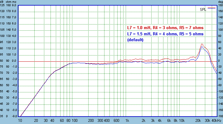
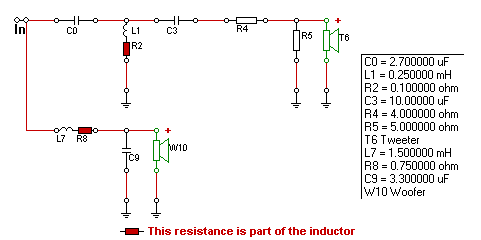
Red is the higher sensisitivity reduced baffle step option for near walls.

rgds, sreten.
Last edited:
Proceed to the follow instructions.Yes I have the drivers
http://www.diyaudio.com/forums/mult...ossovers-without-measurement.html#post2587227
Proceed to the follow instructions.
http://www.diyaudio.com/forums/mult...ossovers-without-measurement.html#post2587227
Hi,
That link is OK but too much emphasis on not needed zobels.
FRD Consortium tools guide
And see Zaph for very good design examples.
rgds, sreten.
http://sites.google.com/site/undefinition/diy
(see if nothing else, the excellent FAQs)
The Speaker Building Bible
Zaph|Audio
Zaph|Audio - ZA5 Speaker Designs with ZA14W08 woofer and Vifa DQ25SC16-04 tweeter
http://audio.claub.net/Simple Loudspeaker Design ver2.pdf
FRD Consortium tools guide
Designing Crossovers with Software Only
RJB Audio Projects
Jay's DIY Loudspeaker Projects
If I was (very) interested in this project (OP), I would have mentioned the drivers name/models/references in the first opportunity.Hi,
That link is OK but too much emphasis on not needed zobels.
(...)
He didn't..
Yes I have the drivers
- Status
- This old topic is closed. If you want to reopen this topic, contact a moderator using the "Report Post" button.
- Home
- Loudspeakers
- Multi-Way
- Matching woofer to tweeter.