You're asking too much without reading the existing documentation- nobody's going to type up a post that's the size of a novella for you on this.
Check out the geddes on waveguides thread, read through it, and you'll have a lot more background from which to ask less comprehensive, more focused questions.
Check out the geddes on waveguides thread, read through it, and you'll have a lot more background from which to ask less comprehensive, more focused questions.
Actually maybe that's a bit harsh since you're only asking about coverage angle-
Sensitivity within the coverage pattern will increase with decreasing coverage angle, essentially approaching behavior of a plane wave tube. For a given speaker distance to a listener, this would generally reduce distortion since the diaphragm has to move less and handle less power.
A key factor for response is the bottom-end. Waveguide depth and coverage angle define LF behavior along with the driver. A narrower pattern for a given mouthsize will load lower as the pathlength is longer.
There's a lot to cover within your question and it's best addressed by lots of reading, simulating, and comparing different horn types to their measured performance.
badman from the first post - yeah it was a bit harsh - with the number of posts in some of those threads - I would wind up retiring before I've finished. ")
badman from second post - when you say "Waveguide depth and coverage angle define LF behavior along with the driver" can you help me understand more. Does Coverage angle have a greater impact than depth, and if so how and what are the trade-offs, ect...???
Ive posted this - without much success - http://www.diyaudio.com/forums/mult...on-radius-validation-any-takers-new-post.html
Let me explain further.
The Woofer and Tweeter I'm using in a 2 way have a 22.3 mm offset between the drivers. I'm using a waveguide first and foremost to eliminate those differences so my tweeter depth is fixed at 22.3.
I've measured the current face-plate on the tweeter and determined the exit angle at close to 5.75 degrees which is also accounted for as my exit angle.
I've got a transition radius up at 76.2mm (3 inches) since in some of my reading - the larger this radius is - the better.
Which basically puts my 1/2 wavelength crossover (2269) within about 15 HZ of the targets for driver spacing.
The diameter of my waveguide matches the diameter of the woofer - 150 mm.
The crux of the matter is that means a coverage angle of 67.205.
So what kind of tradeoffs are present with this current setup as it relates to a fixed depth waveguide (22.3 mm) and a 67.205 coverage angle???
All,
Can anyone explain the effect of a waveguide coverage angle as it relates to effectiveness/distortion/response etc...
Thanks
Some thoughts:
1) The perfect loudspeaker would be infinitely small, have unlimited output, and would radiate spherically.
2) Everything in the loudspeaker constrains the radiation at some bandwidth. For instance, a 1" tweeter with a flange that has a radius of 2.5" will radiate into 180 degrees. This might not seem intuitive; it seems like a 1" tweeter would radiate everywhere, since it's so small. But it doesn't; it radiates into 180 degrees because the baffles limits it's output into a 180 degree semi-sphere in front of the radiator.
3) As you reduce the angle of whatever is baffling the radiator, the angle of radiation is reduced also. For instance, if you go from a flat 180 degree baffle to a conical 90 degree horn, the coverage angle is reduced also.[/b] The coverage angle depends on a gazillion factors so this is a bit of an oversimplification. For instance, if there's diffraction or reflection at the throat, the wavefront won't travel down the waveguide in a perfectly symmetrical fashion. And once that happens, all bets are off. And even worse, all horns and waveguides have reflection and diffraction. So it's not a question of eliminating it, it's a question of reducing it. (The devil is in the details, and it's these pieces that separate real world results from Hornresp sims.)
4) There is a frequency where the wavelength is bigger than the waveguide, baffle or both. At this frequency, directivity will begin to widen, as there's nothing left to constrain it. Going back to my example of a 1" tweeter with a flange that has a diameter of 5", that frequency is 2700hz. So the tweeters directivity will go from 180 to 360 in the octave below 2700hz. (Again, this is approximate; measure it and it will be off by ten or twenty percent.)
As far as waveguide 'effectiveness', you have to define the word 'effective.' If your crossing your tweeter at 3khz, a 5" baffle may be fine. Or you may want a 5" waveguide. It really depends on what your priorities are. Do you want 90 degrees of coverage? 360? 180? 50?
You have to set a goal.
Frequency response is easy. Everything else being equal, I would argue that a waveguide with wide coverage will have smoother response than a waveguide with narrow coverage. You can see this in the frequency response of various speakers. A baffle has 180 degrees of coverage, and tweeters on baffles tend to measure fairly flat. The waveguides in my reference are 90 degrees, and they do not measure as flat as a $50 Dayton RS28 on a flat baffle. So I know that I am giving up some smoothness for directivity control. If you want to see really rough frequency response, take a look at the measurements of some car audio waveguides, where the wavefront is completely asymmetric, due to crazy coverage angles like 90 degrees by 20 degrees. (Check out my 'homster' thread where I measured some.)
Distortion is another one that's fairly easy to predict. Very very narrow angle horns have throat distortion, which is basically due to the high pressure at the throat. Dome tweeters have harmonic distortion, which is caused by the *opposite* problem. Basically the dome experiences high excursion because it's 'pushing' against all the air in the room. (I found this out the hard way, when I tried to DJ an outside party once with home audio speakers. I blew my tweeters, because of excursion.)
If all of that makes sense, I guess I'd break it down into a few categories:
An externally hosted image should be here but it was not working when we last tested it.
1) Category one would be domes in a baffle. Domes in a baffle have well behaved frequency response, but a tendency to distort because they're radiating into 360 degrees at the low end of their bandwidth. (Remember, we transition from 180 to 360 as the wavelengths produced by the radiator exceed the dimensions of the baffle.)
2) Category two would be the very shallow waveguides used by JBL, Mackie and Behringer in their consumer studio gear. The shallow waveguides make the wavefront of the tweeter match the wavefront of the woofer at the xover point, and they also constrain the radiation angle to less than 180 degrees. And since the sound is radiating into a narrower angle, the amount of on-axis energy goes UP. This increase in efficiency allows you to reduce the amount of power going into the driver, which can reduce distortion. All in all, a solid way to use a waveguide, with real benefits.
An externally hosted image should be here but it was not working when we last tested it.
3) Category three would be for loudspeakers with narrower waveguides; perhaps 90 degrees and narrower. At these angles, you'll want a compression driver, to generate the proper wavefront at the apex of the waveguide. The upside to the narrower coverage is less interaction with the room, higher on-axis efficiency, and potentially more 'pinpoint' imaging.
My reference fits into this category and I'm happy with it. For me the best solutions are wide but not too wide, low in distortion but not at the expense of something else, and above all you have to get it right at the throat and at the mouth, or else the whole design doesn't work.
Frequency response is easy. Everything else being equal, I would argue that a waveguide with wide coverage will have smoother response than a waveguide with narrow coverage. You can see this in the frequency response of various speakers. A baffle has 180 degrees of coverage, and tweeters on baffles tend to measure fairly flat. The waveguides in my reference are 90 degrees, and they do not measure as flat as a $50 Dayton RS28 on a flat baffle...
I agree with you that direct radiators on a baffle can be made to give very smooth response, but I think this is largely because they side-step the potential problem of horn resonances.
Where horns are concerned, I think the radiating angle becomes entwined with other parameters, and many of those affect both beamwidth and response ripple.
One caveat - food for thought - consider that long horns with properly sized mouths for their flare profile offer better acoustic loading that some shorter horns or horns with the wrong size mouth. And better acoustic loading usually (always?) gives smoother response.
I'd say there is a "best fit" for length, area expansion, driver and front/rear chambers. Actually, both Don Keele and Marshall Leach said that, albeit in different ways, so I'm just parroting them. Just like sealed or vented systems (or most any other kind of electrical or mechanical system), there is a continuum of alignments, and moving back or forth on the "optimization line" gives trade-offs particular to the optimizations chosen.
I agree with you that direct radiators on a baffle can be made to give very smooth response, but I think this is largely because they side-step the potential problem of horn resonances.
Agreed. I 'came up' in the world of car audio, where asymmetry and narrow horn angles are the norm. And a lot of people go down the 'rabbit hole' of trying to figure out which driver or equalizer will make the horns sound good.
I don't think the problem is the driver or the equalizer; it's the coverage angle.* It's so narrow that you get resonances throughout the entire passband.
I've been building some beolab lenses, and they're really interesting once you realize that they have some of the benefits of horns (directivity control) without the drawbacks (resonances throughout the entire passband.)**
They aren't a 'magic bullet'; nothing is. But they're an interesting variation on horn loading. (Even if they don't look like a horn.)
* technically, the driver *is* part of the problem, because some drivers resonate more than others, depending on the combination of motor, diaphragm and phase plug.
** The Beolab lenses still have resonances, but like a wide angle waveguide, those resonances are less severe
Last edited:
I don't think the problem is the driver or the equalizer; it's the coverage angle.* It's so narrow that you get resonances throughout the entire passband.
Agreed but again, with a caveat. The right length/area is really dependent on the flare profile in addition to the coverage angle. And other things come into play too (as you said in your footnote about motors, diaphragms and phase plugs). So while a long, thin flare might be a problem in some cases, a short, wide flare is a problem in other cases.
The common notion that the larger the mouth, the smoother response is really sort of tied to basshorns, where the mouth area is almost always too small. Keele showed that mouth area can also be too large.
You're underproviding on the info Grok. What drivers on what size baffle? Some pics of what you're trying to build or conceptualizing would be helpful. Generally it's safe to assume that if your W/G is going to be the width of the woofer, including a 3" roundout, then a 90 degree coverage angle is about where you want to be to match directivity. <1" deep? Just make it straight and smooth as can be then break out the microphone to help with the modest amount of reinforcement you should expect at the frequencies where the waveguide is loading.
Keele showed that mouth area can also be too large.
Hi Wayne,
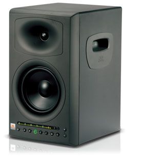
Just to clarify, the conclusion reached in Don Keele’s 1973 "Optimum Horn Mouth Size" AES paper is not correct. He was actually seeing the limitations of his plane wavefront simulation model. An isophase wavefront model such as the one used in Hornresp shows that the amplitude of the ripples in the throat impedance continue to reduce as the horn length is increased and the mouth becomes larger. This result can be readily confirmed in practice by measuring an actual loudspeaker.
Kind regards,
David
Attachments
An isophase wavefront model such as the one used in Hornresp shows that the amplitude of the ripples in the throat impedance continue to reduce as the horn length is increased and the mouth becomes larger.
Where the horn is made longer, this is definitely true. It's just a bigger horn with larger mouth area, closer to an infinite horn. But I definitely see response ripple increased when the mouth is made larger and length is not. This generally implies a larger wall angle. I first noticed it using your program, but of course also see it in measurements of physical devices.
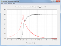
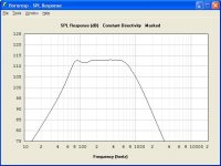
Here's an example. I just took your default Hornresp model, and opened it up a little bit without changing the length. As you can see, ripple increased.
The reason I bring this up is I see a lot of guys taking a shape they think looks right and not even modeling it with your program. It seems there is a perception that bigger mouths always means smoother response, without even looking at the flare profile. But this is not true. The flare profile is important, as is the area expansion and length.
The reason I bring this up is I see a lot of guys taking a shape they think looks right and not even modeling it with your program. It seems there is a perception that bigger mouths always means smoother response, without even looking at the flare profile. But this is not true. The flare profile is important, as is the area expansion and length.
Attachments
-
 Hornresp_flared_horn_response.jpg42 KB · Views: 66
 -
 Hornresp_flared_horn_schematic.jpg31.6 KB · Views: 218
 -
 Hornresp_flared_horn_input screen.jpg58 KB · Views: 221
 -
 Hornresp_default_horn_response.jpg41.7 KB · Views: 223
 -
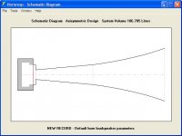 Hornresp_default_horn_schematic.jpg31 KB · Views: 226
 -
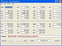 Hornresp_default_horn_input screen.jpg58.1 KB · Views: 269
Issues at Lower Frequencies
1) The shorter the horn the more the peak spreading accross the lower frequuency range. See Fig. 511 (Olsen)
2) The smaller the horn mouth, the larger the peak magnitude at the lower frequencies. See Fig. 510 (Olson)
Regards,
WHG
1) The shorter the horn the more the peak spreading accross the lower frequuency range. See Fig. 511 (Olsen)
2) The smaller the horn mouth, the larger the peak magnitude at the lower frequencies. See Fig. 510 (Olson)
Regards,
WHG
Attachments
The flare profile is important, as is the area expansion and length.
... As very clearly illustrated in the classic Olson charts, posted above by Bill.
Kind regards,
David
Profile attached with feedback/questions
Patrick, Wayne, David,
Thanks for reply's. I'll try and reply in order:
Patrick - The information you responded with made complete sense - (especially the infinitely small aspect of audio... ) you see aspects of this with smaller cabinets too. Should I be concerned with the waveguide radius matching the woofer radius (And I'm talking the actual
I think I'm in category two as you described ring radiator (SB29 rdc) with wider coverage angle and shallower waveguide.
As to my use of "effective" I guess I really don't want to cause more problems attempting a waveguide to offset the physical drivers than just handling the offset with crossover.
Wayne - so how can one tell when the mouth area becomes too large - it seems as if I may wind up dealing with this just due to how shallow my waveguide will be???
David - I originally tried hornresp - since manufacturer does not publish some of the specs needed by application - I cannot accurately model - Do you have other ideas?
All - So how much does the radial versus conical pressure play a role? Also should I try and match the overall diameter to equal woofer diameter (and I'm referring to the top of surround (which in my case is 102 mm and my current waveguide matches the cutout at 150 mm)
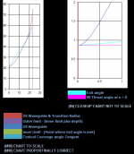
As to my waveguide - I have attached a profile from the XLS sheets I've drawn up - here are the basics
Exit angle - 5.75000 degrees (measured off the original faceplate)
throat radius - 21.94 mm (also measured off the original faceplate)
1/2 cover. angle - 67.20500 degrees
transition radius - 76.2 mm
total waveguide depth -22.5 mm
Baffle width (external) - 246 mm
Again - thanks in advance for your input and experience and continued feedback. It's a learning process for me...
Michael
Patrick, Wayne, David,
Thanks for reply's. I'll try and reply in order:
Patrick - The information you responded with made complete sense - (especially the infinitely small aspect of audio... ) you see aspects of this with smaller cabinets too. Should I be concerned with the waveguide radius matching the woofer radius (And I'm talking the actual
I think I'm in category two as you described ring radiator (SB29 rdc) with wider coverage angle and shallower waveguide.
As to my use of "effective" I guess I really don't want to cause more problems attempting a waveguide to offset the physical drivers than just handling the offset with crossover.
Wayne - so how can one tell when the mouth area becomes too large - it seems as if I may wind up dealing with this just due to how shallow my waveguide will be???
David - I originally tried hornresp - since manufacturer does not publish some of the specs needed by application - I cannot accurately model - Do you have other ideas?
All - So how much does the radial versus conical pressure play a role? Also should I try and match the overall diameter to equal woofer diameter (and I'm referring to the top of surround (which in my case is 102 mm and my current waveguide matches the cutout at 150 mm)
As to my waveguide - I have attached a profile from the XLS sheets I've drawn up - here are the basics
Exit angle - 5.75000 degrees (measured off the original faceplate)
throat radius - 21.94 mm (also measured off the original faceplate)
1/2 cover. angle - 67.20500 degrees
transition radius - 76.2 mm
total waveguide depth -22.5 mm
Baffle width (external) - 246 mm
Again - thanks in advance for your input and experience and continued feedback. It's a learning process for me...
Michael
Attachments
I would suggest modeling that waveguide to make sure its performance is acceptable. I think there are a lot of waveguides out there that never were modeled - the builders assumed if they took a specific profile and connected a throat to a mouth at a desired tangential exit angle, they would have everything they wanted. The trouble is this isn't always true, especially with conicals and similar shapes. I've seen a ton of 'em out there with 5dB ripple, and that's just not acceptable, in my opinion.
David - I originally tried hornresp - since manufacturer does not publish some of the specs needed by application - I cannot accurately model - Do you have other ideas?
As to my waveguide - I have attached a profile from the XLS sheets I've drawn up - here are the basics
Exit angle - 5.75000 degrees (measured off the original faceplate)
throat radius - 21.94 mm (also measured off the original faceplate)
1/2 cover. angle - 67.20500 degrees
transition radius - 76.2 mm
total waveguide depth -22.5 mm
Baffle width (external) - 246 mm
Hi Michael,
If you don't have the driver parameter values, then set Eg = 0 to give the driver diaphragm a constant rms velocity of 10 cm/sec.
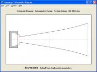
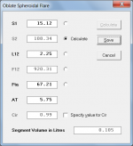
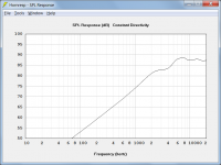
I have attached screenprints showing the Hornresp input parameter values for your specified waveguide, and the resultant power response. All driver parameters apart from Sd have been left at their default values because they are not used in the calculations when Eg = 0. Sd has been set equal to the throat area - a different value can be specified if desired, but it will simply change the absolute level of the SPL chart without altering the shape of the curve. I have assumed the worst-case scenario of radiation into free space. Because Cir = 0.99, the 108.34 sq cm mouth area will be sufficient.
The horn throat entry half-angle has been set to 5.75 degrees to match that specified for the driver. The horn mouth flare tangent angle has been set to 67.21 degrees to match that specified for the coverage half-angle. The axial length has been set to 2.25 cm to match that specified for the horn / waveguide.
The Hornresp Directivity tool will give you an idea of the on-axis / off-axis pressure response.
Kind regards,
David
Attachments
David - Thanks!
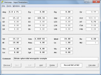
So how did you set the OBL instead of CON in Hornresp? I do have some limited info from measurements I took at home of this driver - I can post later tonight.
Which means I need to learn more about using hornresp. Can I post some of my actual measurement data tonight and have you look into it?
So how did you set the OBL instead of CON in Hornresp? I do have some limited info from measurements I took at home of this driver - I can post later tonight.
Which means I need to learn more about using hornresp. Can I post some of my actual measurement data tonight and have you look into it?
So how did you set the OBL instead of CON in Hornresp?
Can I post some of my actual measurement data tonight and have you look into it?
Hi Michael,
To select the Obl oblate spheroidal waveguide option, press O when the L12 length parameter input field has the focus in Edit mode - it's all in the Hornresp Help file...
.By all means post any driver data that you may have, for everyone (not just me) to look at.
Kind regards,
David
- Status
- This old topic is closed. If you want to reopen this topic, contact a moderator using the "Report Post" button.
- Home
- Loudspeakers
- Multi-Way
- Coverage Angle for Wave Guides