I was refering to your simulations and my measurements. I phrased that oddly I know. A more natural way would be "my measured curves is in close agreement with the model". But from scientific point that is nonsense, IRL is what it is, then a model can be in agreement with reality, not the other way around. Frequency response is measured with Dayton Omnimic.
Also with the IMF modeling it looks good but it seems that the pipe contributions are exaggerated. If you could lower the pipe output by 5 dB or so?
Also with the IMF modeling it looks good but it seems that the pipe contributions are exaggerated. If you could lower the pipe output by 5 dB or so?
OK, understood. I can't lower the pipe output - it is turned on by selecting the output switch to show sound pressure at the radiator face (the plane of the pipe where it exits into the room). Is your mic measurement at the exit plane of the pipe?
I am not sure what I am doing wrong but the single-fold case is not agreeing at all. Are your dimensions in the sketch correct because I get the main bass peak at about 75 Hz with the dimensions you provide (see below). ?
I am not sure what I am doing wrong but the single-fold case is not agreeing at all. Are your dimensions in the sketch correct because I get the main bass peak at about 75 Hz with the dimensions you provide (see below). ?
Attachments
75 Hz is less than 1 m pipe length? Please note that the internal hight is 0.82 m so the geometric length of the pipe must be more than 1.5 m and with 5:1 taper that should be well below 50 Hz. My guess that is a for a pipe of 0.82 meter in lenght not internal hight.
I'm off to battle that middle age spread
I'm off to battle that middle age spread
Sim of DaLine - again
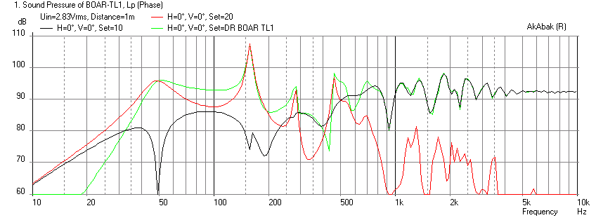
I found a typo in my earlier sim's geometry - sorry about that. I think the three harmonic peaks have similar amplitudes now, but the fundamental freq is higher at 50 Hz.
Here is the measurement:

This is the sim with the T/S params as measured:
This one is too far off - must be something wrong in the sim still. I will look at it again later when I have some time.
I found a typo in my earlier sim's geometry - sorry about that. I think the three harmonic peaks have similar amplitudes now, but the fundamental freq is higher at 50 Hz.
Here is the measurement:
This is the sim with the T/S params as measured:
This one is too far off - must be something wrong in the sim still. I will look at it again later when I have some time.
Attachments
Last edited:


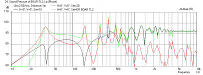
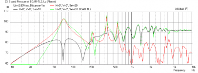
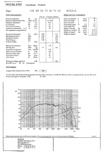
Black is direct radiation from driver and red is vent radiation - at the plane of cone or vent. Green is combined output 1 m away. Note that this color convention is for purposes of comparing with Dr Boar's plots. Usually I have red as direct driver radiation and green as vent, and black as combined in all my other sims posted elsewhere.
I calculate the 1/4-wavelength resonant frequency for a pipe length of 1.64 meters and tapered at 5:1 to be ~37 Hz.
Paul
Paul
75 Hz is less than 1 m pipe length? Please note that the internal hight is 0.82 m so the geometric length of the pipe must be more than 1.5 m and with 5:1 taper that should be well below 50 Hz. My guess that is a for a pipe of 0.82 meter in lenght not internal hight.
I'm off to battle that middle age spread
I calculate the 1/4-wavelength resonant frequency for a pipe length of 1.64 meters and tapered at 5:1 to be ~37 Hz.
Paul
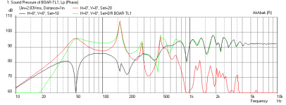
The revised sim in post 25 has 37 Hz right on.
Took your specs, mixed with the peerless specs and modeled this. Problem is the driver only has an Xmax of 2mm. This is easily exceeded with a few watts without a high pass which defeats the point of going TL. Even then, this looks to more suited for use as a midrange than a midbass and would be better suited for a sealed box.
Attachments
The scope at hand is to study the resonance patterns of various ways of folding a TLS. To this end any decent driver will do.
I do have the Peerless SX14H aka 850108 that has a an Xmax of 4.5mm that I can use for mesurements.
I have done some experiments with damping of the pipe, if it pans out, I will make separate thread of those findings. But here I want to investigate foldings as such in quarter wave pipes not develop a speaker system with box, damping, drivers and crossover.
The scope at hand is to study the resonance patterns of various ways of folding a TLS. To this end any decent driver will do.
I do have the Peerless SX14H aka 850108 that has a an Xmax of 4.5mm that I can use for mesurements.
I have done some experiments with damping of the pipe, if it pans out, I will make separate thread of those findings. But here I want to investigate foldings as such in quarter wave pipes not develop a speaker system with box, damping, drivers and crossover.
There's one other variable associated with the mechanical makup of the TL you don't seem to have included, and that is driver placement. One of the major contributors to resonant peak damping is locating the driver part way along the line. I did exactly that with my Poor Plumber's Pluto speakers shown here... Poor Plumber's Pluto DIY project
I agree that driver placement along axial distance of TL is the major way to tune the response to minimize the harmonic peaks. Typically, placing at a point between 0.2x to 0.33x is a good place to start and one of the major ways a simulation is helpful in optimizing driver placement. However, for BLH designs with a driver chamber, which these designs all seem to resemble, have a limited location for the driver.
I intentionally set the driver fairly close to the closed end to keep the system "clean"
1. Pipe placement
2. Chamber size as a low pass filter
3. Having two drivers along the line to spread the harmonics
4. Two separate lenght pipes or of two different flares could spread the resonances
5. Massloading the the pipe opening by vent or passive radiator (flapping transmission line!)
6. Internal helmholz resonator traps for reducing harmonics
7. Building the cabinet in Celotex so the flex will absorbe some of the peaks.
There are many things to try out but I would get lost in a maze of permutations and I do not want to get into something that I need multivariate analysis to sort out, this is a hobby!
Last edited:
How about that--math done correctly equals reality!
Paul
Paul
The revised sim in post 25 has 37 Hz right on.
Driver placement on the end make matters worse not better.
Port determines system Q and driver placement only! Length defines the ¼ wave frequency. With proper driver placement the 2nd harmonic can be nulled, something that cannot be done with end loading the line. Placement and amount (medium suggested) of dampening material is critical to null the second harmonic. This is typically only near the driver itself, not the typical 1/3-2/3rds of the line. Doing so greatly reduces low end output. Also note that use of heavy dampening at the bottom (1-1.5") helps reduce harmonics, without reducing output. Port placement should be at the end of the line, typically set this within 1-1.5" from the bottom ie just above the heavy dampening.
Port determines system Q and driver placement only! Length defines the ¼ wave frequency. With proper driver placement the 2nd harmonic can be nulled, something that cannot be done with end loading the line. Placement and amount (medium suggested) of dampening material is critical to null the second harmonic. This is typically only near the driver itself, not the typical 1/3-2/3rds of the line. Doing so greatly reduces low end output. Also note that use of heavy dampening at the bottom (1-1.5") helps reduce harmonics, without reducing output. Port placement should be at the end of the line, typically set this within 1-1.5" from the bottom ie just above the heavy dampening.
When doing an ML-TL with a port, not a tapered TL with its terminus at the very end of the line, I've found two geometries that almost always work best. If the driver is located at ~20% of the line's length from the closed end, the best location for the port will usually be 3-4" from the end of the line. If the driver is located at ~1/3 of the line's length from the closed end, the best location for the port is usually ~10" from the end of the line. I define "best" as an overall flat response from the knee in the curve on up with a nicely rounded knee, and I've attached an example system bass response graph depicting "best". YMMV, of course.
Paul
Paul
Driver placement on the end make matters worse not better.
Port determines system Q and driver placement only! Length defines the ¼ wave frequency. With proper driver placement the 2nd harmonic can be nulled, something that cannot be done with end loading the line. Placement and amount (medium suggested) of dampening material is critical to null the second harmonic. This is typically only near the driver itself, not the typical 1/3-2/3rds of the line. Doing so greatly reduces low end output. Also note that use of heavy dampening at the bottom (1-1.5") helps reduce harmonics, without reducing output. Port placement should be at the end of the line, typically set this within 1-1.5" from the bottom ie just above the heavy dampening.
Attachments
If the driver is located at ~20% of the line's length from the closed end, the best location for the port will usually be 3-4" from the end of the line. If the driver is located at ~1/3 of the line's length from the closed end, the best location for the port is usually ~10" from the end of the line.
I concur with these observations for a MLTL - the port is rarely located at the lowest point possible when looking at how clean the output is. Also, placing driver between 20% and 33% seems to work but an inch can make big difference, and the only way to tell is to simulate it. 10 inches from the bottom for port location may work, but is kind of too much from the "open" end to call it open anymore - I have gone as high as 7 or 8 inches and that is usually better than 1.5 or 2 inches.
When doing an ML-TL with a port, not a tapered TL with its terminus at the very end of the line, I've found two geometries that almost always work best. If the driver is located at ~20% of the line's length from the closed end, the best location for the port will usually be 3-4" from the end of the line. If the driver is located at ~1/3 of the line's length from the closed end, the best location for the port is usually ~10" from the end of the line. I define "best" as an overall flat response from the knee in the curve on up with a nicely rounded knee, and I've attached an example system bass response graph depicting "best". YMMV, of course.
Paul
If you would post up driver and enclosure info and I'll see if your design criteria match mine. I rather doubt it does, have yet to see any driver placed @20% work with a low Q port. Now if your designing a BR/TL may work (= high Q port) but even then doubt the second harmonic is nulled.
Most acoustic desings would utterly fail if RF. Only passable because of the room / harmonic node masking.
I'm willing to bet most do not understand the significance between high aspect ratio / low Q ports and low aspect ratio / high Q ports and how this affects driver placement along the line.
Just because something is different or inconsistent with your rules of thumb for the location of drivers and ports doesn't mean it can't work (obviously, the sim shows that it does). It is a highly non linear system of coupled differential equations with an infinite solution space, so to make categorical statements like yours is not really justified in the physics or the math.
Last edited:
- Status
- This old topic is closed. If you want to reopen this topic, contact a moderator using the "Report Post" button.
- Home
- Loudspeakers
- Multi-Way
- Pipe fold geometries and harmonic patterns