When folding a pipe TLS, horn or other quarter wave resonanators, folding can affect how higher harmonics is exited. If the aim of a folded pipe is to get maximum radiation resistance at the fundamental resonanse and as little as possible of the higher harmonics, fodling should work toward this aim. That is that the folding geometry should intrinsically reduce unwanted harmonics. Damping material in the pipe should then be icing on the cake.
I plan to use some scrap material to build some pipes of different geometries and measure the resonanse pattern of the pipes. Measuring output at pipe opening and also near field output from the cone (to see if I can detect dips in response corresponing to peaks at the pipe output)
I have started with two pipes each about 150 cm long 4:1 taper (20x20cm to 5x20cm) one folded once and the other twise similar to the IMF TLS. I intend to drive the pipes with a Peerless 5.5" driver.
Suggestions for other folding geometries?
From a scientific standpoint the reference should be a unfolded pipe with the same length and taper, but it hardly represent a practical TLS. If no interesting suggestions are made I might build a Baily type of TLS. Then the taper is different as well as the folding but is a used geometry at least.
measurements will be impedance plots (Woofer Tester 3) and frequency response (Omnimic) Measurement points are opening of the pipe and also nearfield of the driver to see if peaks of pipe output correlate with dips in driver output.
Suggestions about pipes and measuremet techniques are wellcome

The port affects Q of the system and position of the driver. Adjust the drivers position so that you null the second harmonic. Minimal stuffing of the line with most if not all dampening directly behind the driver. Modeling shows a small offset of a little more dampening material below than above is common. When doing this recheck the measurements as you can go too far one way or the other depending on density and placement. Also 1-1.5" heavy dampening (pad) at the bottom helps. Do not do anything to the top, we want this reflection. Adding more to the line will reduce the peaking up high but really only reduces output at the bottom end. Little can be done to reduce the third harmonic other than physical taper used.
These shorter twists and turns actually increase the peaking up high due to the shorter distance between bends and the internal reflections they induce. They do help in reducing higher frequencies at the port, while increasing them internally. Prefer to make three folds with the port exiting near the driver. If this is floor loaded creates a tapped horn.
A guy named Tom Cox did a study similar to the OP's plan years ago. IIRC, it was published in Speaker Builder Mag. The bad news is, Audio amateur Publications has disolved with the death of Ed Dell. Dell's web site used to offer for sale, back issues of SB. Now, it's successor, audioXpress is even a shadow of it's former self and is buried in amongst other audio hobbiest rags at elektor int'l publications..... audioXpress | Combining great articles, projects, tips and techniques for producing the best in quality audio, audioXpress connects manufacturers and distributors with audiophiles eager for sound solutions.
This graph is what started me with folds and harmonics. As you can see a single fold gives the best suppression of harmonics. Tyrland had both driver and pipe opening on the top surface.

In my case I have the driver on the forward face and the opening at the top rear. Measurements are at the center of the pipe opening and 1-2 cm in front of the dustcap of the driver (NF, near field). I have different foldings, like IMF, folded once and a untapered one Daline.
I start with the IMF folded one. Drivers are two PP cone 5” woofers with Fr of about 60 Hz. The Peerless one has a Q of 0.5 and the Taiwan one a Q of 1.0. Pipe:22 cm wide and taper from 20 to 5 cm.

Pretty much as I expected. 3-7th harmonic is clearly seen. Note that the peak output is at 40 Hz while the dip in driver response is above 45 Hz.

Sam pipe but with the high Q driver
Here there are peaks all over 500-1500 Hz! Note that the peak output is below 40 Hz while the dip in driver response is above 45 Hz.
Now it is time to investigate that pipe folded once that is supposed to intrinsically tame that third harmonic. . Pipe:22 cm wide and taper from 20 to 5 cm.
Lets start with the Peerless again

Not that the fundamental has more of a peak and it also matches the dip in driver response. The 3rd and 5th harmonic is the same and the 7th is worse. Not what I had hoped for.

Very broad fundamental and harmonics that is no improvement.
Then I have the Daline fold. That is a top chamber and then 3 equally wide pipe section of 5.5cm with the opening at the very bottom of the rear panel.

Here the Q of the fundamental is lower, harmonics similar to the IMF fold. Here the peak output of pipe and dip in NF is matched.

Very low Q fundamental and some peak suppression in the 500-800 Hz range.
I do have impedance measurements as well but then I will overload the post.
It does seem that the harmonics is not only due to pipe geometry but that features of the driver comes into play.
There is obviously a lot to learn. More to come…
Last edited:
Skip the previous post!
I have made more carefully matched measurements and then the harmonics follows the pipe and is not affected by the drivers. (The Taiwan drivers is tricky to seal that might have been the cause).The finding that the pipe folded once is no better or worse than the IMF stands. In a way that is good news.
I have made more carefully matched measurements and then the harmonics follows the pipe and is not affected by the drivers. (The Taiwan drivers is tricky to seal that might have been the cause).The finding that the pipe folded once is no better or worse than the IMF stands. In a way that is good news.
I have Stridbeck/Tyrland speakers that are very similar to the IMF TLS80. However, Tyrland published a graph that folding the TLS only once reduced the third harmonic by 10 dB compared to the IMF way of folding.
Post 5 top image
I build the two variants in smaller scale as well as a untapered TLS in 3 sections the DaLine.
Measurements and layout are drawn with a felt pen on the side. Internal width is 20 cm. I have tried to make the pipes in all 3 of equal length and having the taper the same in the IMF and the pipe folded once. But there was some limitations due to the scrap material I had at my disposition.
Measurements were in sets of six.
1. Peerless driver near field of driver open pipe
2. Peerless driver near field of driver closed pipe
3. Peerless driver mid of pipe opening of open pipe
4. Taiwan driver mid of pipe opening of open pipe
5. Taiwan driver near field of driver open pipe
6. Taiwan driver near field of driver closed pipe
This to minimize microphone movement between for the same driver with open and closed pipe and also minimize the movement of microphone in the pipe when measuring output from two different drivers. The stuffing is about 250 g of BAF roll that was inserted into the pipe opening the end of the roll was folded once and tightly jammed into the opening, the impedance curves suggest that it behaves as a closed box.
I measured the Thiele Small parameters and also for the driver in the closed pipe.
To compare the output of the pipe I have adjusted the peak to the same level as driver output. To do a proper addition radiating surface and phase angles has to be taken into account, so this is just for comparative reasons.
The result is that the 3rd harmonic is +10dB the 5th +6 dB and 7th at about 0 dB compared to the fundamental for both the Peerless and the Taiwan driver. The pipe suppress the driver output by 5 dB or more between 40 and 50 Hz but below that the driver is less protected than in a closed box.
So to conclude this first part the harmonics are substantial as measured from the pipe opening as well as indicated by the near field measurements of the cone with dips and peaks in output correlating with the harmonics.
The signal sweep in Omnimic sound very hollow, like talking trough a metal duct.
Post 5 top image
I build the two variants in smaller scale as well as a untapered TLS in 3 sections the DaLine.
Measurements and layout are drawn with a felt pen on the side. Internal width is 20 cm. I have tried to make the pipes in all 3 of equal length and having the taper the same in the IMF and the pipe folded once. But there was some limitations due to the scrap material I had at my disposition.
An externally hosted image should be here but it was not working when we last tested it.
Measurements were in sets of six.
1. Peerless driver near field of driver open pipe
2. Peerless driver near field of driver closed pipe
3. Peerless driver mid of pipe opening of open pipe
4. Taiwan driver mid of pipe opening of open pipe
5. Taiwan driver near field of driver open pipe
6. Taiwan driver near field of driver closed pipe
This to minimize microphone movement between for the same driver with open and closed pipe and also minimize the movement of microphone in the pipe when measuring output from two different drivers. The stuffing is about 250 g of BAF roll that was inserted into the pipe opening the end of the roll was folded once and tightly jammed into the opening, the impedance curves suggest that it behaves as a closed box.
I measured the Thiele Small parameters and also for the driver in the closed pipe.
An externally hosted image should be here but it was not working when we last tested it.
An externally hosted image should be here but it was not working when we last tested it.
An externally hosted image should be here but it was not working when we last tested it.
An externally hosted image should be here but it was not working when we last tested it.
To compare the output of the pipe I have adjusted the peak to the same level as driver output. To do a proper addition radiating surface and phase angles has to be taken into account, so this is just for comparative reasons.
An externally hosted image should be here but it was not working when we last tested it.
An externally hosted image should be here but it was not working when we last tested it.
The result is that the 3rd harmonic is +10dB the 5th +6 dB and 7th at about 0 dB compared to the fundamental for both the Peerless and the Taiwan driver. The pipe suppress the driver output by 5 dB or more between 40 and 50 Hz but below that the driver is less protected than in a closed box.
So to conclude this first part the harmonics are substantial as measured from the pipe opening as well as indicated by the near field measurements of the cone with dips and peaks in output correlating with the harmonics.
The signal sweep in Omnimic sound very hollow, like talking trough a metal duct.
Dr Boar,
Very nice work and very meticulous measurement - as always from you. I see these harmonics in my AkAbak sims all the time and wonder how much makes it out the opening but you have confirmed they indeed make it out. Can you share your exact build geometry and driver specs? I will model in AkAbak and we can compare simulations and measurements. I will need to know exact speaker placement relative to back wall and mic position.
Regards,
X
Btw, OT... but I saw your antique corner horn project and was going to sim that but the 3d geometry makes it tricky. Maybe you have a detailed plan of CSA vs distance that you have from your drawing that includes the 180 deg turn?
Some designs use as many 90 deg sharp turns as possible to act as low pass filters to suppress the harmonics. We should see some effect here as more turns are introduced. Stuffing is normally only used in the driver chamber and should suppress some of the higher frequencies but probably not the 3rd harmonic - still too low for fibers to affect. If one puts stuffing in actual horn passages it really attenuates the bass gain of the LF in addition to the HF. This is an interesting study though.
MJK's alignment table document contains the following regarding stuffing:
"Classic transmission lines exhibit ripples in the pass-band. This is a property of
the design that can be mitigated by the driver placement and the location and density of
the fiber stuffing. Adjusting the amount and location of fiber stuffing helps reduce the
ripples but at the expense of bass performance. One scheme is to place stuffing only at
the locations of the highest air velocities for the quarter wavelength modes targeted for
suppression. This usually means stuffing the first 2/3’s to 3/4’s of the transmission line
length and leaving the last 1/3 to 1/4 of the length nearly empty. In general, add or
remove fiber stuffing to tune the final enclosure to your system, your room, and your
personal taste."
To me, stuffing 2/3 to 3/4 of the line seems a significant amount. Again, here, stuffing should be done with a combination of imp. measurements and listening tests - all to suit the builder's voicing preferences of course.
I mesurements hand written as Google Draw is "waiting for connection". The leftmost box is the DaLine in 11mm OSB the other two in 12mm MDF.
I am not sure what you mean by backwall. With the microphone in the nearfield the room does not enter the equation.
I typed a much longer reply but then my token had expired and I had to start all over


I am not sure what you mean by backwall. With the microphone in the nearfield the room does not enter the equation.
I typed a much longer reply but then my token had expired and I had to start all over


The one fold pipe.
The first I notice is that the signal sweep in Omnimic sounds way less hollow. If this is due to change in harmonics or the fact that the opening is at the opposite side of the box I do not know.
If we normalize the harmonics to the fundamental peak the 3rd: is about + 6dB and that is 4-5 dB better than the IMF, the 5th is the same as the IMF and the 7th harmonic is worse by a couple of dB. I think this is a better folding than the IMF, not as dramatic as in Tyrlands measurements but still.
Stuffing at the first 40-50% of the pipe shold be enough. The fundamental that has it velocity maxima at the opening is left alone. You catch the 3rd harmonic at ⅓ of the length you catch the 5th harmonic both at ⅕ and ⅖ of the lenght and the 7th at 1/7 ⅖ and 3/7. That should be a pretty good start!


Last edited:
I mesurements hand written as Google Draw is "waiting for connection". The leftmost box is the DaLine in 11mm OSB the other two in 12mm MDF.
I am not sure what you mean by backwall. With the microphone in the nearfield the room does not enter the equation.
I typed a much longer reply but then my token had expired and I had to start all over
What is the final vent dim on the IMF ? 40 or 46 mm? Could not quite make out your writing. I only wanted the back wall distance for he final integrated output from driver port and reflected from back wall.
Sim of DaLine
Dr Boar,
Here is the simulation of the Daline TL. I am not sure which one to compare to because you say to ignore the previous post? If I compare with your Daline measurements:
I get this:

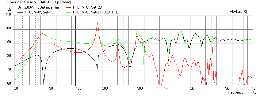
The harmonics seem to match but the fundamental is off (meas is 40 Hz, sim is 50 Hz)??
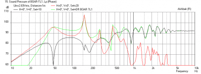
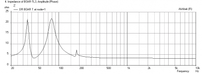
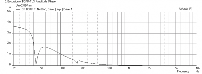
Anyhow, let me know what you think. I color coded it the same as yours: black is driver direct radiation and red is the emission from the port. Green is the overall combined output at 1 m away.
- Freq response
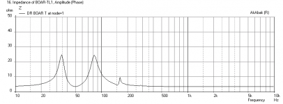
- Impedance
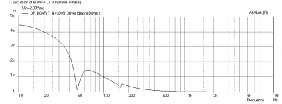
- Cone displacement
Dr Boar,
Here is the simulation of the Daline TL. I am not sure which one to compare to because you say to ignore the previous post? If I compare with your Daline measurements:
I get this:
The harmonics seem to match but the fundamental is off (meas is 40 Hz, sim is 50 Hz)??
Anyhow, let me know what you think. I color coded it the same as yours: black is driver direct radiation and red is the emission from the port. Green is the overall combined output at 1 m away.
- Freq response
- Impedance
- Cone displacement
Attachments
Last edited:
Now I have made som final measurements on the DaLineR with the Peerless driver. At the moment I am listening to The Commitments the original soundtrack, one chanel only and through that Peerless, no crossover no tweeter. It sounds good
On the floor 300 mm in front of concrete wall measured 1 m in front of driver. Unsmoothed and to 1/6th octave.

This is the data for the acual driver used as measured by Woofer Tester 3.
* Manufacturer: Peerless
* Model: 830343
* Piston Diameter = 108.0 mm
* f(s)= 63.93 Hz
* R(e)= 3.31 Ohms
* Z(max)= 22.26 Ohms
* Q(ms)= 2.951
* Q(es)= 0.515
* Q(ts)= 0.439
* V(as)= 7.868 liters (0.278 cubic feet)
* L(e)= 0.55 mH
* n(0)= 0.38 %
* SPL= 87.90 1W/1m
* M(ms)= 9.29 grams
* C(ms)= 0.67 mm/N
* BL= 4.90
The impedance curve in the model is not far of from the acual curve apart from that the real one has a much lower peak at 30 Hz of 10 Ohms instead of 20 Ohms.

Also the predicted frequency cuves are quite close

As is the pipe and driver output
The real measurements show lower Q than the predicted model with less sharp dips in frequency dip at the fundamental and less deep at the harmonics. The fundamental also looks flatter (lower Q) IRL than model, the Q of the harmonics are in closer agreement. At normal listening levels the cabinet OSB parts vibrates to a degree that is easy to feel with a hand on front or back panel. Could it be losses in the cabinet that lower the Q of the fundamental? This box has sides of 12 mmMDF but all other parts of 11mm OSB. The other boxes are all made of 12 mm MDF
Last edited:
My morning coffe kicked in.
If I do the same in room measurement with the pipe open and stuffed close, the differences will show how the pipe output contribute regardless of room resonanses.
Compared to the closed pipe I get +5dB around the fundamental, +10 dB at the third harmonic at 150 Hz and then a sharp peak followed by a dip at the 5th harmonic at about 250 Hz. Time to add some external braces to the cabinet to see of that will bring up the Q of the fundamental.


Sim of IMF with measured driver T/S params
Dr. Boar,
Here is the sim of the IMF speaker. Let me know what you think...
Here is your measurement:
Here is the AkAbak sim:
second plot below is impedance, last is the cone displacement.
Dr. Boar,
Here is the sim of the IMF speaker. Let me know what you think...
Here is your measurement:
Here is the AkAbak sim:
second plot below is impedance, last is the cone displacement.
Attachments

- Status
- This old topic is closed. If you want to reopen this topic, contact a moderator using the "Report Post" button.
- Home
- Loudspeakers
- Multi-Way
- Pipe fold geometries and harmonic patterns