Many people want to get backward radiation to as higf Fq as possible, but I'm not so sure about it being wise. I for example have windows right behind the speaker, and they are like mirrors at high Fq - too much reflections???
Heavy drapes would help breakup and absorb these glass reflections.
I can see you asking Aino to open / close while you listen
")
There's definitely a good reason to have the rear wave as closely matched to the front (tonally) as possible- but the transfer function as perceived by the listener is what needs to be matched, not necessarily the rearward radiation. If you have a highly reflective surface behind the speakers, then you'd want to either damp it or adjust the rearward output to avoid having a bright reflected tonal balance.
I have a rather cool setup in which my living room (which houses the big rig and is more of a mancave than anything else) joins to the kitchen and dining spaces with only one section of wall, and open doorways etc. The speakers are directed so as to fire the rearwave into those back spaces- so I get sound wherever I am, but the rear reflections are well delayed. For me, since I listen passively from behind regularly, it's critical that the rear lobes match the front reasonably well (or at least are properly balanced).
I have a rather cool setup in which my living room (which houses the big rig and is more of a mancave than anything else) joins to the kitchen and dining spaces with only one section of wall, and open doorways etc. The speakers are directed so as to fire the rearwave into those back spaces- so I get sound wherever I am, but the rear reflections are well delayed. For me, since I listen passively from behind regularly, it's critical that the rear lobes match the front reasonably well (or at least are properly balanced).
OMG!!! Those David Pellegrine's amt+double wg measurements are from heaven on a sunny day! This makes me really hungry!

David's woofer is in a frame that is far form ideal as a dipole. It should be relatively easy to find the right diameter for a nudie mid to xo around 2kHz LR4 and end up with consistent directivity.
Many people want to get backward radiation to as higf Fq as possible, but I'm not so sure about it being wise. I for example have windows right behind the speaker, and they are like mirrors at high Fq - too much reflections???
I can't take full credit for this design. I built these for a client and he had everything speced out for me other then we started with the Morel Cat378. I reported back to him that they just where not getting the job done with this design. He then sent me the AMT2560 to try. I was shocked on how well it did in the waveguide. I had the speakers set up 6' from the front wall with a damping panel on the wall directly behind each speaker, 4' from the side walls and toed in just in front of my listening position. That is where I found them to sound best. I also tried them in my living room which is 25' x 25' with 11' ceilings, hardwood floors on half the floor and a wall of glass on one side. I found them a bit bright especially at higher volumes. I have no daming in this room. Tried but the wife said NO!
This is actually a 2.1 system with a dipole sub. Here is a build thread if anyone is interested.
Open Back Speaker Build
Dave
Hi Dave:
The periodic ripple you see at the bottom of the w/g range may be related to 2 things- the baffles are not properly rounded/beveled, so you're getting some edge diffraction (though it's significantly lower in level thanks to the directivity) and also the final transition on your w/g has a harder edge- particularly in the verticals. Some (teased so it's loose) felt around the perimeter of the edge at the mouth would likely be a very worthwhile tweak to suppress some of the ripple.
The periodic ripple you see at the bottom of the w/g range may be related to 2 things- the baffles are not properly rounded/beveled, so you're getting some edge diffraction (though it's significantly lower in level thanks to the directivity) and also the final transition on your w/g has a harder edge- particularly in the verticals. Some (teased so it's loose) felt around the perimeter of the edge at the mouth would likely be a very worthwhile tweak to suppress some of the ripple.
My biggest hurdle with waveguides is using them in an MTM setup. No possible way to get the spacing correct, well unless you block off part of the M's when doing so.
She would not want me to build another set. What it looks like isn't the problem, but she'd freak if I'd pulled a Cal Weldon on her! (We've been down that road before
Sad too as I have a couple dozen different designs in my head ATM.
Dave, you should try out the Dayton Audio AMT2-4 ( similar to Airborne rt4001) or the Mini8-4 (airborne rt 20021) with a waveguide. Should be a winning combination. Far less $ than others = good price performance ratio would make them popular IMHO.
Greebster, some have done a pretty good job of limiting CTC spacing with waveguides- often that means routing the midwoof cutouts with the waveguide already mounted, and removing some of the plastic, so the flange doesn't get in the way as much.
That's what was done on some (presumed) DDS waveguides in these custom JBL-based systems:
Full Size Image
That's what was done on some (presumed) DDS waveguides in these custom JBL-based systems:
An externally hosted image should be here but it was not working when we last tested it.
Full Size Image
Hi Dave:
The periodic ripple you see at the bottom of the w/g range may be related to 2 things- the baffles are not properly rounded/beveled, so you're getting some edge diffraction (though it's significantly lower in level thanks to the directivity) and also the final transition on your w/g has a harder edge- particularly in the verticals. Some (teased so it's loose) felt around the perimeter of the edge at the mouth would likely be a very worthwhile tweak to suppress some of the ripple.
I agree the baffle edges are to sharp. Especially on the rear guide. Before we went to the rear waveguide the wings where not notched out. The cabinet finish was done so that was really the only way I could fit the guide without getting into the finish.
On the vertical are you saying something like RAAL does but with thinner felt?
I've done a little bit of testing with the baffle edges to see what I could come up with that was simple to do and seams to work well. This is a guide I'm working on for myself that wraps around the mid. The baffle edges are 30 degrees plus a 60 degree cut where it meets the cabinet. Then the edges are sanded to a slight round over. This is done with a 3/4" baffle with 2" strips glued around the edges to make it a total of 1-1/2" thick. This seems to work well for diffraction and is pretty simple to do on a table saw.
SpinMonster
This started as an RS150/ XT25TG30 combo for the top of a three way. I ended up switching out to the ER18 and the LD25X. Although twice the money IMO i think well worth it.
I don't believe the LD25X is available with the removable face plate any more which you need for these guides.

Dave
I agree the baffle edges are to sharp. Especially on the rear guide. Before we went to the rear waveguide the wings where not notched out. The cabinet finish was done so that was really the only way I could fit the guide without getting into the finish.
On the vertical are you saying something like RAAL does but with thinner felt?
Yes, though I'd use it all the way around- your waveguides terminate in an angle rather than a fully flat (or rounded/rolled back) surface. While they're better in this respect than many horn/waveguides, there are several that do this better- the SEOS, the OSWGs from both geddes and the DDS variant, the QSC, etc. Of course, you're optimizing for certain factors, which I get- it has to fit, after all, and your polar performance is nothing if not impressive.
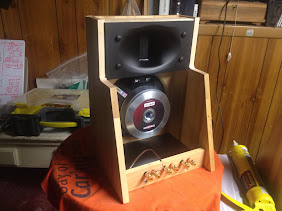
Foam or felt allows you to mitigate any diffraction over that lip while still retaining the same flange size. Basically you want to approximate a forward continuation of the profile, with whichever lossy material you use, so it doesn't screw up what's already good, but acts more like a larger roundover. Pic is the JBL Progressive Transition horn/waveguide as used in the Econowave project, with shaped foam extending the profile and killing the hard edge.
The shaped waveguide you show is pretty awesome way of incorporating it into the baffle. Heck of a job! Don't mind the fugly "test mule" style build, or the pine needles on the carpet- the foam is the key!
An externally hosted image should be here but it was not working when we last tested it.
Foaming At The Mouth Article By Jeff Poth
Last edited:
Greebster, some have done a pretty good job of limiting CTC spacing with waveguides- often that means routing the midwoof cutouts with the waveguide already mounted, and removing some of the plastic, so the flange doesn't get in the way as much.
That's what was done on some (presumed) DDS waveguides in these custom JBL-based systems:
An externally hosted image should be here but it was not working when we last tested it.
Full Size Image
Depends on where it's crossovered at. If we can dig much deeper this issue is lessened altho remains. I've done trimming of the flanges on both midrange, midbasses and waveguides, then using clay/felt/foam to fix, but one can only go so far once we get up higher. Simply not enough room. You are correct the problem is the edge diffraction when doing so, this energy is reflected back down the throat akin to back EMF, a high vSWR in antennas. Dr. Geddes solution using reticulated foam really works in this regard. Have done testing using the same about an eon ago with the same type he uses is the same as what I had been using for speaker grills as early as the late '70's. The high vector diffusion of such is quite practical in reducing this effect.
Another means to reduce this effect is rounding the waveguide flange like JMLC and Azura horns use. Albeit making them larger causing greater issue with CtC spacing. Personally think if this were a normal two or three way the sharp edge can be rounded over with a oval or ring of foam, sculpted felt etc. Clay helps to fill voids. Tapering off near the closest driver.
If it weren't for pottery clay deforming while in the kiln I'd whip out dozens. Bone dry greenware is bloody fragile so only works for the person that made it. Can think of several types of glaze that would make them look stunning if the shape could be maintained within tolerance.
Here's an idea, back dampen a commissioned Dale Chihuly blown glass horn. He's a true master artist
The foam grille is what I'm planning to do to the shown JBL cabs- Reticulated foam grille, with some higher density absorption closer to the walls. I'm thinking 1/4" cork all along the inside of that lip (if you take a close look, there's about a 2" "lip" all the way around the baffle), and 2" reticulated foam across the whole thing. If I get the absorption right, it'll push the directional bandwidth a smidge lower than an equivalent flat-baffled setup, and should sound pretty great.
Between the JBL components, DDS horn, and fiberglass coated cabinet (dear lord it's stiff), they're potentially reference-level speakers, if I make sure to deal with that lip right and possibly tweak the XO a bit.
Between the JBL components, DDS horn, and fiberglass coated cabinet (dear lord it's stiff), they're potentially reference-level speakers, if I make sure to deal with that lip right and possibly tweak the XO a bit.
My biggest hurdle with waveguides is using them in an MTM setup. No possible way to get the spacing correct, well unless you block off part of the M's when doing so.
Ahem. From our own "speaker dave":

In theory you are correct, as long as there is no galling on the threads and the nut doesn't hang up it won't spin the stud and act like a puller and break the adhesive bond.
As in automotive when installing an exhaust manifold the stud bottoms out into a blind hole there is no danger of separation unlike the tweeter plate where the bottom of the hole is the ceramic magnet. A tight thread can force the stud to spin like a bolt and cause damage. Just a tip for those that may not realize it.
You're not helping things making a big deal of something thats just not the case. I'm getting messages asking if this can potentially damage the tweeter with this and the answer is no...0%. If you are afraid of damage, put in the stud with loc-tite to prevent it from turning. Once it sets then put on the nuts. Satisfied?
The cap is just flattening the gain- you're double counting. It's 10-12dB total.
But that's okay- terrific performance, makes me want to get some and try it out. Certainly the pricepoint is an impressive achievement for that level of performance.
Yes, I was aware of the issue in my typed message but unlike other forums that allow you to edit forever, this forum chooses to lock out edits after a certain amount of time which is a mistake as demonstrated here. My post will now stand uncorrected and we will likely have more corrections posted with them not seeing that you and I already caught it. Just smile when you see it.
At 2000hz, the distortion is over 20db lower because the F2 is generated by what happens at 1000hz. Since the cap continues to lower noise as you go down in frequency, it cleans up the distortion in the upper sections beyond the amount that the WG is lifting response. Yes the cap is flattening the gain but the dstortion is not just 10-12db lower. Testing shows it to be as much as 25db on some tweeters. 10-12 comes from lowering the direct 2k gain and the rest comes from lowering further what happens lower in frequency that generates F2-F5 harmonics. So it matters that the cap is starting at 8K but continuing lower than the active cross at 1700.
By the way, tests have been done on XT25s on 12" WGs that show you can cross as low as 1200 with this tweeter with low distortion. The cap is also muting the resonant frequency from ringing like a bell.
The phase plugs on these ring radiators are why they work better higher in frequency.
Dave, can you make a WG that has a phase plug shaped like the XT25's suspended in the throat by 2 or 3 tiny pins to accomplish the same thing with conventional dome tweeters so you can start with a cleaner unit?
Dave, can you make a WG that has a phase plug shaped like the XT25's suspended in the throat by 2 or 3 tiny pins to accomplish the same thing with conventional dome tweeters so you can start with a cleaner unit?
I keep coming back to this in your original post,
"I chose the 8x5 unit for limited vertical but excellent improved horizontal dispersion although I hear no drop in highs standing up as I did with the bare XT25. Horizontal dispersion is wall to wall"
Spinmonster, as far as I am aware waveguides actually do the opposite, reduce dispersion of the tweeter. Seems to be a common misconception that they do the opposite.
Im not having a go at you, Im intending on using a very similar combo myself,
See this post for a better explanation,
http://techtalk.parts-express.com/s...the-ND20-in-a-waveguide&p=1933216#post1933216
I keep coming back to this in your original post,
"I chose the 8x5 unit for limited vertical but excellent improved horizontal dispersion although I hear no drop in highs standing up as I did with the bare XT25. Horizontal dispersion is wall to wall"
Spinmonster, as far as I am aware waveguides actually do the opposite, reduce dispersion of the tweeter. Seems to be a common misconception that they do the opposite.
Im not having a go at you, Im intending on using a very similar combo myself,
See this post for a better explanation,
Curious about the ND20 in a waveguide
The internet is a great source of info but not everything is correct. The post above is using the term wave guide but I dont know which one it is. They may have used a horn that isnt a WG. Please understand that wave guides and horns are not always the same thing. Some horns are designed to limit and focus response. This one isnt. I will leave the definition to someone who actually knows what he is talking about but a wave guide is a horn but a horn isn't always wave guide. I hope I worded that correctly. Where is Geddes when you need him?
I posted the graphs showing/proving VERY improved high freq dispersion. That is physical evidence and not hearsay or subjective impression. The vertical while less than the horizontal is still improved over a bare unit but it doesn't have the low freq extension the 8" dimension has. In the vertical plane it acts as a 5" WG. In the horizontal it acts as a 8".
Dispersion is so improved that the tweeter unlike its bare application has no limited sweet spot and sounds good anywhere in my 21x21 foot room. No exaggeration.
Last edited:
Beau- it's not wider, just more consistent, that's what he means by better. The tonal balance doesn't change when moving around as it can with an "unloaded" tweeter.
It is wider. When people talk about limited off axis response, they're talking about dispersion. At 45 degrees off axis, there isnt a fall off like the bare tweeter so at that frequency, it is wider dispersion. The 2nd sentence is 100% correct.
Im not sure I agree, take this as an example,
http://www.htguide.com/forum/showth...eguide-testing&p=545877&viewfull=1#post545877
In the first measurement we see consistent dispersion up until about 3.5k, then a drop in off axis spl as frequency increases.
In the second measurement we see a consistent off axis response that mirrors the on axis response right from 2k through to the top octave.
The waveguide you are using displays similar characteristics in that it makes the off axis response more consistent, as Badman stated. The fact that it boosts the bottom end and reduces distortion is a given, no argument from me on that point .
- Status
- This old topic is closed. If you want to reopen this topic, contact a moderator using the "Report Post" button.
- Home
- Loudspeakers
- Multi-Way
- My first wave guide speaker....lots of pics