I doubt that's the case. It looks like a very nicely thought-out and executed project. What I find especially interesting is that the measurements seem to show that Dave's WG removes the actual problem I've heard from the Vifa and ScanSpeak ring radiators: extremely extremely narrow treble dispersion.
That, by contrast, I suspect that would end up disappointing. Not because it wouldn't be good, but because there wouldn't be much improvement from what you already have. Probably get more people on forums to ooh and aah if you're able to throw out brand names like Audio Technology, Accuton, Scan Revelator, etc, but ultimately speakers really boil down to three things: listening axis FR, dispersion, and output capability. Your current project looks well-sorted for a speaker of that size. I'd say be happy, and add multiple subs.")
Thank you. The lack of comments on the actual system had me thinking I wasted all the hours it took to document everything.
If you look at my pics in my original post you will see I run 4 15" TC sounds subs powered by 8000 watts.
I'm in sonic heaven right now.
Thanks again.
Taking a closer look at how a wave guide/cap lowers distortion at frequencies over the crossover. Since a cap starts operating from a much higher freq to counter the lift of the guide, it is lowering distortion from above the cross freq.
Here is the bare tweeter distortion plot

Here is the distortion plot with guide and cap. The F2 distortion is down by 25db at 2000hz and the response is again flat on the tweeter. Its not just low in frequency. Since the harmonics generate the noise up top that theyre based on, the F2 is down 15db from 6-10k Hz. Whats really interesting is that the higher order distortion is based on whats happening from the low end hiccups and thus the F4 and F5 is sent to the floor on the top of the range. Active crossover uses can use any slope they want countering the phase issues electronically. The roll off approximates an LR2 with just a cap. I dont know how to build passives but if you can then increase the crossover to LR4 from 1800 or so, the low end issues are off the map including the res freq ringing like a bell.

1700 is not too low for an XT25 using a wave guide.
Here is the bare tweeter distortion plot
Here is the distortion plot with guide and cap. The F2 distortion is down by 25db at 2000hz and the response is again flat on the tweeter. Its not just low in frequency. Since the harmonics generate the noise up top that theyre based on, the F2 is down 15db from 6-10k Hz. Whats really interesting is that the higher order distortion is based on whats happening from the low end hiccups and thus the F4 and F5 is sent to the floor on the top of the range. Active crossover uses can use any slope they want countering the phase issues electronically. The roll off approximates an LR2 with just a cap. I dont know how to build passives but if you can then increase the crossover to LR4 from 1800 or so, the low end issues are off the map including the res freq ringing like a bell.
1700 is not too low for an XT25 using a wave guide.
Last edited:
Nice work Spin, thanks for the detailed write-up.
Looks like I'll have to get my xt25's reconed (connected to sub amp channel on active system.. Oooops) and make some guides.
All nitpicking aside, seems like some clear advantages to adding a waveguide to the xt25.
Cheers
Dean.
Looks like I'll have to get my xt25's reconed (connected to sub amp channel on active system.. Oooops) and make some guides.
All nitpicking aside, seems like some clear advantages to adding a waveguide to the xt25.
Cheers
Dean.
While I'm at it. Does anybody know where I could get my xt25tg30-04 reconed or buy a kit?
Sorry for the OT, back to normal progam.
Dean
The are not made to be fixed. The units are $35 for the better 60 model so its probably best to just upgrade
This is absolutely correct by the way. There is some gap flux addition, but the main effect is stray field reduction. The front plate also gets saturated, which reduces flux modulation. It is a Band-Aid however since this technique is an expensive waste of magnet volume.
Why is there a Hall sensor in a cell phone? How can it be used as you indicate?
Not sure why Earl, really do not know why. Have seen mention of an application where one could be tracked using magnetic field lines of force tho. You know, there's an APP for that! lol
Android Play store has several apps that allow direct reading of what is happening the Accelerometer (Gyro) and magnetometer (3 axis Hall) in 3 axis. Example : https://play.google.com/store/apps/details?id=com.innoventions.sensorkineticspro&hl=en
There are many others on the market that will display the results of all the sensors built into most every Android device.
For the Trekie in me I use Tricorder also, which is a spin on ST the Next Generation Tricorder. Friend was laughing this afternoon when he asked someone if they were mic'd (a joke). Whipped out my phone and did a full body scan (with sound effects). Too funny.
Taking a closer look at how a wave guide/cap lowers distortion at frequencies over the crossover. Since a cap starts operating from a much higher freq to counter the lift of the guide, it is lowering distortion from above the cross freq.
Here is the bare tweeter distortion plot
Here is the distortion plot with guide and cap. The F2 distortion is down by 25db at 2000hz and the response is again flat on the tweeter. Its not just low in frequency. Since the harmonics generate the noise up top that theyre based on, the F2 is down 15db from 6-10k Hz. Whats really interesting is that the higher order distortion is based on whats happening from the low end hiccups and thus the F4 and F5 is sent to the floor on the top of the range. Active crossover uses can use any slope they want countering the phase issues electronically. The roll off approximates an LR2 with just a cap. I dont know how to build passives but if you can then increase the crossover to LR4 from 1800 or so, the low end issues are off the map including the res freq ringing like a bell.
1700 is not too low for an XT25 using a wave guide.
I stand corrected, thank you
My other concern tho would be with excursion eg low end acoustic output. But with the waveguide helping alot here doesn't appear to be an issue.

I stand corrected, thank you
My other concern tho would be with excursion eg low end acoustic output. But with the waveguide helping alot here doesn't appear to be an issue.
The wave guide boosts 10db. After that you add in that the cap is starting to filter from 8000hz so by 1700 thats another 12db. The cap is filtering me past where the 4th order electrical was with what I guess is a 5th order electrical filter below 1700. I blew up quite a few bare tweeters which was the total system spl limit. Its hitting peaks far beyond where the 4th order electrical cross at 2000 was. At the listening position its 7db higher and the mid amps are now clipping so even thats not the limit. 5th order at 1700 minus 10db isnt more excursion than 4th order at 2000 was.
As a test, the mid amp is now the system limit even with me putting the crossover at 1500 4th order. 1700 isnt even close.
Also understand the reason I went to 1700 was to stop activating the 3000hz trigger for the twin peaks at 6k and 9k on the RS180. Had that not been the mid, I could cross higher if I used a scan speak midbass crossed at 2000hz.
Last edited:
I know Dave Pellegrene has a waveguide for an AMT he used on his site. Its actually a dipole speaker. Scroll down about 30% of the page. He has tests done on the combo. Using a WG on an AMT will make its low end clean for the same reasons. Looks like he used an AST 2560
https://plus.google.com/photos/101632266659473725850/albums/5845603116946836977?banner=pwa
He took all of the work out of them because the tweeter of your choice mounts easily unlike the huge effort previous projects show like Zaph's.
https://plus.google.com/photos/101632266659473725850/albums/5845603116946836977?banner=pwa
He took all of the work out of them because the tweeter of your choice mounts easily unlike the huge effort previous projects show like Zaph's.
Last edited:
Have been on Dave's site on several occasions.
Perhaps next build, if SHE[\b] doesnt kill me before then
I was bound by "she" also. Mine looked commercially built and was narrow enough to pass. The next living room system cant be big and it cant be black so I have to have an automotive paint finish and likely a bit smaller. It will have this wave guide with this same tweeter though. Diffraction is another negated issue with WG's so I can go narrower on the baffle with no ill effect.
As in the auto industry, studs bottoming entails nothing more that finger tightening them to be touching and not tool tightening them that they apply any pressure. There is no mechanical pressure being applied to the front plate of the tweeter.
I cant edit my other response and I just caught what you said.
Studs have nuts that turn independent of the stud. Tightening a bolt isnt the same as a nut on a stud. Turning a bolt pushes the shaft down. Tightening a nut pulls the stud upward and doesnt turn it at all.
The reason a stud has to bottom out is so it doesnt turn as you turn the nut which is exactly what happened as I tried to tighten them. Being too short, the stud would go lower until there were no threads inside the nut and it went flush with the wave guide plate.
In theory you are correct, as long as there is no galling on the threads and the nut doesn't hang up it won't spin the stud and act like a puller and break the adhesive bond.
As in automotive when installing an exhaust manifold the stud bottoms out into a blind hole there is no danger of separation unlike the tweeter plate where the bottom of the hole is the ceramic magnet. A tight thread can force the stud to spin like a bolt and cause damage. Just a tip for those that may not realize it.
OMG!!! Those David Pellegrine's amt+double wg measurements are from heaven on a sunny day! This makes me really hungry!

David's woofer is in a frame that is far form ideal as a dipole. It should be relatively easy to find the right diameter for a nudie mid to xo around 2kHz LR4 and end up with consistent directivity.
Many people want to get backward radiation to as higf Fq as possible, but I'm not so sure about it being wise. I for example have windows right behind the speaker, and they are like mirrors at high Fq - too much reflections???
David's woofer is in a frame that is far form ideal as a dipole. It should be relatively easy to find the right diameter for a nudie mid to xo around 2kHz LR4 and end up with consistent directivity.
thats kind of what i am building right now, crossing over from a minimal baffle jantzen ja8008 at 2500hz, to a dipole RAAL with SEOS waveguide.
i dont use a rear waveguide though. not sure if its really needed...?
Many quote very high distortion numbers for speakers. They typically quote 1% THD (-40dB)
Am I reading the data presented here correctly?
@ 2kHz the basic distortion is ~-46dB relative to the fundamental. Or ~ 0.5% at that test SPL level.
With the waveguide fitted and the series capacitor the distortion has dropped to -70dB relative to the fundamental at that same 2kHz. As I understand it -70dB is equivalent to 0.03% THD. Is this correct?
What is the SPL of the test frequency when the distortion was measured?
Does the distortion vary when the SPL levels are varied?
In particular, if the continuous power handling were X watts, then when driven at XmW (-30dB ref max), would the distortion be lower?
I know Dave Pellegrene has a waveguide for an AMT he used on his site. Its actually a dipole speaker. Scroll down about 30% of the page. He has tests done on the combo. Using a WG on an AMT will make its low end clean for the same reasons. Looks like he used an AST 2560
https://plus.google.com/photos/101632266659473725850/albums/5845603116946836977?banner=pwa
He took all of the work out of them because the tweeter of your choice mounts easily unlike the huge effort previous projects show like Zaph's.
Heil AMT1 And The Heil Horn Article By Jeff Poth
Light on documentation but sure is big enough to load pretty low.
The wave guide boosts 10db. After that you add in that the cap is starting to filter from 8000hz so by 1700 thats another 12db.
The cap is just flattening the gain- you're double counting. It's 10-12dB total.
But that's okay- terrific performance, makes me want to get some and try it out. Certainly the pricepoint is an impressive achievement for that level of performance.
- Status
- This old topic is closed. If you want to reopen this topic, contact a moderator using the "Report Post" button.
- Home
- Loudspeakers
- Multi-Way
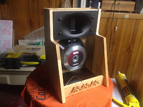
- My first wave guide speaker....lots of pics