
I've just bought these drivers for a 2 way design which I will start building next week -
Woofers are Peerless HDS-164 AL
FR/Tweeters are Tangband W2-800SL
Big thanks to Mondogenerator for his great help so far, now I need to make a decision on the x/o parts and crossover frequency. My main concerns are BSC and keeping the component number down to a minimum. I may put the TB in an open backed baffle but will need to protect them from over stress, its a bit of an experiment with these.
The TB has an large impedance spike just under 200 hz or so, but looks well behaved in the treble, a little rise above 10khz. The 6.5" Peerless has some break up around 6-7khz I think, the spike is not large, and not too bad for a metal cone. I will angle the baffle to time align the drivers and roll off the tops a little
I thought the x/o point shd be around 800hz.
So a 1st with an impedance notch, or a 2nd order linkwitz to keep it safe and simple? The notch wd require a large value cap so thats another consideration.
Last edited:
You should make test. 1st order can work (12dB acoustic slope).
But I think 24dB acoustic slope works better with metal cone (18dB with notch/18dB)
I think the drivers have chance to be incompatible. The Perless is an other class of sound. You'd better put a tweeter instead, the 810921 is an obvious choice.
But I think 24dB acoustic slope works better with metal cone (18dB with notch/18dB)
I think the drivers have chance to be incompatible. The Perless is an other class of sound. You'd better put a tweeter instead, the 810921 is an obvious choice.
Thanks Jerome, yes I need some equipment and buy a windows laptop, I can only run basic stuff on a Mac. Thats the problem atm.
Reason for the tweeter choice was just I wanted to cross lower than normal and also I'm on a tight budget. I've heard it compares v well soundwise to the small Alpairs, in the mid/treble.
I think I will go with a 2nd order Linkwitz crossed around 750hz, with a one/third octave space between the points to hopefully create some baffle step comp.
Last edited:
Jerome whilst i respect your opinion I fail to see how the 2 drivers are incompatible The W2 is really a midtweeter and the peak at Fs should be less problem than a tweeter Fs at 500hz + surely?
I believe Bill is intending on OB mids - hf. However, Used in a sealed volume of 50cc the F3 is at ~500hz. A 2nd order HP would increase to 4th order acoustic, or thereabouts. Certainly better than the same filter on a low Fs tweeter in terms of excursion and THD I should think.
The 'fly in the ointment' with the W2 is the 4 Ohm coil meaning some large component values.
I suggested a cap plus notch (as this was what i would do), however it may not suit Bill. Im sure 2nd order LR would work just as well.
Those Peerless do look nice, however i doubt the TBs are in a lower class, they are very good within their limits.
Last edited:
Noob question, because the impedance on the TB's are rising at x/o point (750hz), will I need to insert a value higher than 4 ohms into the calculator?
I'm roughly calculating (linkwitz 2nd) if I insert 5 ohm for the TB, 8 ohm for the Peerless
high pass @ 795 hz
cap 20uf inductor 2.0 mh
low pass @ 660 hz
cap 15uf inductor 3.8mh
I'm roughly calculating (linkwitz 2nd) if I insert 5 ohm for the TB, 8 ohm for the Peerless
high pass @ 795 hz
cap 20uf inductor 2.0 mh
low pass @ 660 hz
cap 15uf inductor 3.8mh
Last edited:
Noob question, because the impedance on the TB's are rising at x/o point (750hz), will I need to insert a value higher than 4 ohms into the calculator?
I'm roughly calculating (linkwitz 2nd) if I insert 5ohms for the TB, 8 ohms for the Peerless
high pass @ 795 hz
cap 20uf inductor 2.0 mh
low pass @ 660 hz
cap 15uf inductor 3.8mh
Online calculators are really just a shot in the dark.
Hi,
A first order series x/o is the first thing you should try.
It will interact quite well with increasing bass driver impedance
and the fundamental impedance peak of the midrange/tweeter.
Note it must be series, not parallel first order, as the former
will interact well with the impedances, the latter will not.
rgds, sreten.
Last edited:
Hi Bill, If you are planning on doing text book crossovers you will probably need to use some impedance compensation (have you read through AllenB's designing loudspeakers without measurememts thread?)
If you simulate the crossover from measurements (real or traced from manufacturers specs) you will better be able to do a crossover without the need for impedance compensation. For you goal of simplest crossover, simulation (especially if you use something with an optimizer) will probably allow you to get more minimal whilst still retaining good sound.
Tony.
Jerome whilst i respect your opinion I fail to see how the 2 drivers are incompatible The W2 is really a midtweeter and the peak at Fs should be less problem than a tweeter Fs at 500hz + surely?
...
In an objective way no problem, all drivers match. You are right
")
But how can you match the sound of these drivers ? I not not sure subjectively the marriage will be ok.
I tried to make this kind of speaker : a SEAS 8" magnesium, a Fountek FR88EX and the two drivers sound very different.
I think the reason is there is a level of quality of sound between the two brands. Perless sounds far better.
A high end tweeter is a better choice, the SEAS 27TBCG is an other choice.
I encourage Bill to make experiments to get his own opinion
Jerome, some of the Seas woofers have really big spikes around 4-5khz, are you sure that wasnt messing with the sound?
a thread on the TB over at tech talk
TB W2-800SL FR and distoration measurement plots
a car install using Omnes 2.01's, basically the same driver
http://www.talkaudio.co.uk/ipb/index.php/topic/285487-a-little-install/
The dip around 3-9khz shd give a smoother vocal sound (I'm guessing), the rise above 10khz is probably ok, good for cymbals and 'air'
Sreten, thank you, thats really interesting about using a series 1st order if it can control that 90ohm spike on the TB's
Last edited:
http://www.falconacoustics.co.uk/downloads/Peerless/835025.pdfJerome, some of the Seas woofers have really big spikes around 4-5khz, are you sure that wasnt messing with the sound?
A first order crossover is a poor choice with this woofer, IMO.
http://www.falconacoustics.co.uk/downloads/Peerless/835025.pdf
A first order crossover is a poor choice with this woofer, IMO.
because of the breakup? I was going to cross around 600 hz if it was a 1st order
Last edited:
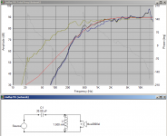
Hi Bill, Attached is a sim (just of the TB) with your suggested 2nd order at 795Hz.
red is the target accoustic response 795Hz 2nd order LR
green is the original curve traced from spec sheet, no baffle step modeling.
blue is with your proposed 20uF, 2mH
black is after running the optimizer in Speaker workshop (which gave around 30uF and 1.5mH)
note I simply set the target spl at 90 I've not looked at the woofer.
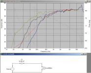
With just a single cap things get a bit ugly. The impedance peak does mess things up a lot more. (second attachment shows with just 34uF cap)
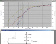
edit: adding some impedance compensation (which needs a big cap!) can get closer with a single cap.
Just posting to give you an idea how a sim can help out
Tony.
red is the target accoustic response 795Hz 2nd order LR
green is the original curve traced from spec sheet, no baffle step modeling.
blue is with your proposed 20uF, 2mH
black is after running the optimizer in Speaker workshop (which gave around 30uF and 1.5mH)
note I simply set the target spl at 90 I've not looked at the woofer.
With just a single cap things get a bit ugly. The impedance peak does mess things up a lot more. (second attachment shows with just 34uF cap)
edit: adding some impedance compensation (which needs a big cap!) can get closer with a single cap.
Just posting to give you an idea how a sim can help out
Tony.
Attachments
Last edited:
Sreten, thank you, thats really interesting about using a
series 1st order if it can control that 90ohm spike on the TB's
Hi,
Well basically it does, bucketloads more than parallel first order.
rgds, sreten.
FWIW I don't post much here anymore, because I'm fed up
with trying to correct erroneous posts in the threads I post in.
If your drivers have a suitable sensitivity mismatch for BSC,
and you pick the x/o point to match cabinet BSC there is
a good chance 1st order series could work relatively well.
FWIW also just triangulating the top of a standard cabinet,
back top corner to the front baffle, chamfering the rear
of the driver and stuffing the rear space is the simplest.
It will be a lot less grief than open baffle with a simple x/o.
understood about limiting your posts etc, btw the spike is more 25-30 ohm not 90
 I was looking at the wrong side lol.
 Drivers are both around 87, the woofer only slightly higher - so with that in mind I'm curving the baffle and stuffing the rear of the 'open' baffle as much as possible as well as 'spacing' the x/o point to create a dip in the midrange - I hope I won't need a resistor.
 the design is this shape from the side
Last edited:
Thanks v much for this, thats really kind.
I've just tried to download some software but it wasnt compatible with excel for Mac
so this cheered me up no end
yes a notch requires a great big cap - wd it make much of a difference if it was a series 1st?
Hi Bill, I have no experience with series crossovers so I could not say, but from Sreten's post I would assume that the impedance peak is not an issue.
My original post I was composing whilst he posted his suggestion (so sorry Sreten if it seemed I was contradicting you!). Certainly if you get your windows env up and running you should be able to simulate either series or parallel networks, and see how each works.
The software I used for tracing the manufacturers curves was splcopy SPL Copy - Speaker Frequency Response Automatic Trace Tool it is much easier to use than spltrace.
I then loaded it into splviewer SPL Tools to "normalize" the frd file to go from 10Hz to 20Khz (with 4096 points).
Third I loaded the resultant spl file (and zma which is not normalized) into Jeff Bagby's Response Modeller Loudspeaker Design Software and extracted the phase. You can do a LOT more than this, such as model the low end response and add in baffle step effects, I just used the manufacturers spl curve as it was a demo of what you can do. You should match to your baffle at least.
Then I imported the normalized / phase added, spl and zma files into speaker workshop (though Jeff's PCD is probably better when getting started) and put in your suggested 795 hz crossover point and calculated values.
I Then ran the optimizer over the range of 100Hz to 10,000Hz and rounded the resultant values of cap and coil to close to normal values.
For the impedance compensation I told speaker workshop to add in for a resonant peak at (from memory) 160 Hz. the result was quite different to what I presented. It did take out the peak but wasn't optimal for adjusting the spl curve. I then tried the optimiser which gave an 800uF cap, so scrapped that
I played with the values manually then and that was what was posted in the third graph. The whole process didn't take very long, but shows you the power you have available with the right tools. Great for getting an idea of how particular drivers might work together. I personally would do real measurements and then use those for the actual crossover design, but you can do it purely from the manufacturers curves. see http://audio.claub.net/Simple%20Loudspeaker%20Design.pdf
Also Charlies page software
Attached are the frd zma and speaker workshop project files.
Tony.
Attachments
Last edited:
- Status
- This old topic is closed. If you want to reopen this topic, contact a moderator using the "Report Post" button.
- Home
- Loudspeakers
- Multi-Way
- 2nd order or 1st with notch, that is the question