Nelson Pass said:
My point would be that 45 degree corner reflectors might
only make a subtle difference, but they do so on several
fronts. They do stiffen the enclosure, they do allow a more
accurate taper with a folded pipe, and they do provide some
reflective/diffusive effects which reduce unwant internal
resonance. Having tried it both ways, I find that I prefer
the sound, what else can I say?
Hmm, as I noted, my experience mirrors BB's measurements/conclusions, so unless the cab is designed to use reflectors, simple corner glue blocks made from scraps work just fine for stiffening up the corners and the requisite stuffing sufficiently attenuates reflections back through the driver, so I'm curious what's causing the differences you're hearing, unless you're designing around reflectors, then comparing with/without them Vs a cab that's properly folded.
GM
Re: Hi GM
I meant the alignment would 'ring' excessiviely due to the huge Fb peaking. This is normally caused by way too much Vb and/or too high a tuning, and no amount of polyfil stuffing that MJK's worksheets will factor in will attenuate it enough and it doesn't allow us to choose fiberglass, wool, etc., so based on your listening review I'm doubtful the plot is accurate, but we need to look at the design to see what the actual plot should be and figure out what needs to be done to the design to further improve its in-room response.
GM
Could you explain to me how you can tell that the cabinet is ringing from the plot I posted. I punched in a number of different stuffing densities, up to 2 lbs/ft and it only nominally changed the curve. Perhaps I'm missing something.
I meant the alignment would 'ring' excessiviely due to the huge Fb peaking. This is normally caused by way too much Vb and/or too high a tuning, and no amount of polyfil stuffing that MJK's worksheets will factor in will attenuate it enough and it doesn't allow us to choose fiberglass, wool, etc., so based on your listening review I'm doubtful the plot is accurate, but we need to look at the design to see what the actual plot should be and figure out what needs to be done to the design to further improve its in-room response.
GM
Folded and unstuffed line measurements
It appears that some of you built some TL (or ML-TQWT) having a folded line.
My problem is that in the scientific literature (Webster Horn Equation eventually applied to musical instruments, like trumpets and so on) it is often quoted that folding has effects on resonances, the fundamental and so on.
Translated in some other language it appears that Leff is dependent upon the frequency.
This can be disturbing in TL's and ML-TQWT's where the position of the driver (and the port) is critical.
Unfortunately until now I' haven't found (on the Net) anything quantitative (and predictive).
In order to understand the problem I need to correlate the physical design with the measurements (with the line unstuffed).
Any contribution ?
Thanks
GM said:Hmm, as I noted, my experience mirrors BB's measurements/conclusions, so unless the cab is designed to use reflectors, simple corner glue blocks made from scraps work just fine for stiffening up the corners and the requisite stuffing sufficiently attenuates reflections back through the driver, so I'm curious what's causing the differences you're hearing, unless you're designing around reflectors, then comparing with/without them Vs a cab that's properly folded.GM
Since I happen to be building up some in the next two weeks,
I'll see about making a measurement. Of course, if you are
stuffing the tube sufficiently, that's another item, but I notice
that a lot of the TQW crowd doesn't seem to be stuffing at the
fold.
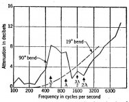
This would be a repeat of the same picture posted elsewhere
to what amounts to the same question. It is Beranek's plot
of attentuation vs frequency for a bent duct having a 1 foot
diameter (or its equivalent). My point being that a 45 degree
strike plate would show some sort of difference.
to what amounts to the same question. It is Beranek's plot
of attentuation vs frequency for a bent duct having a 1 foot
diameter (or its equivalent). My point being that a 45 degree
strike plate would show some sort of difference.
Attachments
Setting questions of effect on line length etc. aside, I've always figured that it was nearly mandatory in order to break up standing waves in the section of pipe in question. I once did a four-fold transmission line and regarded the flat, parallel ends of each section of the line as resonances waiting to happen. Given that there were four pairs of opposing surfaces, all the same distance apart, any standing waves would have been reinforced beyond tolerance. Putting diagonals in each corner was an easy solution.
Though I know the math is different, I am just as suspicious of sudden changes in tube cross section in transmission lines as I would be in horns. You're setting up a non-linearity in the impedance. Putting a diagonal plate in the corner helps ease the transition.
Grey
Though I know the math is different, I am just as suspicious of sudden changes in tube cross section in transmission lines as I would be in horns. You're setting up a non-linearity in the impedance. Putting a diagonal plate in the corner helps ease the transition.
Grey
- Status
- This old topic is closed. If you want to reopen this topic, contact a moderator using the "Report Post" button.