Well there are low DCR electrolytic caps used in switching supplies, tie their cathodes together and ya got a bipolar 😉
^ 😛
Garry I didn't answer your question about how I calculated the resonance. I cheated and used an online calculator --> Resonant Frequency Calculator
Tony.
Garry I didn't answer your question about how I calculated the resonance. I cheated and used an online calculator --> Resonant Frequency Calculator
Tony.
Fixed!!
You won't believe it . . . .
I removed the 1.8mH coil from the board to isolate from everything else. Clipped it between the amp and woofers w/ alligator clips. No distortion.
So then I soldered the cap to the coil, and clipped both into the woofer circuit. Still no distortion.
Soldered them both back to the board, but not tied down, connected the woofers via the terminals on the board and tested again. Still no distortion.
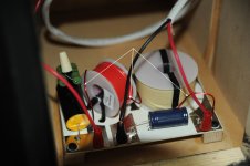
Then I tied the coil down with the wire twist ties I'd been using (see photo comment #23). Distortion is back!
Removed the twist ties, distortion is gone again. Removed the twist ties from the coils on the right speaker xover, tested it. No more distortion there, either.
LESSON: Don't secure coils to a PCB board with wire twist ties!
I assume the coil induces a field in the wire tie, which is then induced to the board trace where the tie passes through.
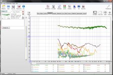
Anyway, THD is now about -47 db, or < 0.5%. And they sound great; very smooth. Plot below has no smoothing:

So now I have new caps and coils coming that I really don't need.🙁
Thanks for suggestions, everyone!
You won't believe it . . . .
I removed the 1.8mH coil from the board to isolate from everything else. Clipped it between the amp and woofers w/ alligator clips. No distortion.
So then I soldered the cap to the coil, and clipped both into the woofer circuit. Still no distortion.
Soldered them both back to the board, but not tied down, connected the woofers via the terminals on the board and tested again. Still no distortion.
Then I tied the coil down with the wire twist ties I'd been using (see photo comment #23). Distortion is back!
Removed the twist ties, distortion is gone again. Removed the twist ties from the coils on the right speaker xover, tested it. No more distortion there, either.
LESSON: Don't secure coils to a PCB board with wire twist ties!
I assume the coil induces a field in the wire tie, which is then induced to the board trace where the tie passes through.
Anyway, THD is now about -47 db, or < 0.5%. And they sound great; very smooth. Plot below has no smoothing:

So now I have new caps and coils coming that I really don't need.🙁
Thanks for suggestions, everyone!
Last edited:
Well there you go!! Get some nylon cable ties 🙂 I guess that the twist ties have a ferric wire in them and that is interacting with the coil. Glad you tracked it down!
You could probably return the ordered parts. Most places will accept returns if the goods are unused. Or you could keep then for your next project 😉
Tony.
You could probably return the ordered parts. Most places will accept returns if the goods are unused. Or you could keep then for your next project 😉
Tony.
Under our noses all along. What would Miss Marple say?...see photo comment #23
<snip>
LESSON: Don't secure coils to a PCB board with wire twist ties!
Fixed!!
You won't believe it . . . .
.....Then I tied the coil down with the wire twist ties I'd been using (see photo comment #23). Distortion is back!
Removed the twist ties, distortion is gone again. Removed the twist ties from the coils on the right speaker xover, tested it. No more distortion there, either.
LESSON: Don't secure coils to a PCB board with wire twist ties!
I've have put this one into my treasure trove of "special" troubleshooting problems.... What a tale to tell!!!
Congratulations on finding the problem - and for teaching us all a little lesson!!!
Then I tied the coil down with the wire twist ties I'd been using (see photo comment #23). Distortion is back! Removed the twist ties, distortion is gone again.
LESSON: Don't secure coils to a PCB board with wire twist ties!
I assume the coil induces a field in the wire tie, which is then induced to the board trace where the tie passes through.
Aah! I see the twist ties in your photo now...funny how our minds see what they want to...a black nylon ziptie.
BTW, congrats on the methodical testing and finding the source.

I have encountered similar distortion with poor core material, although not to this degree.
I figured a quick test was in ordered: Grabbed a 1mH air core from the parts box along with a 47uF cap and 4 ohm load resistor.
The test measured frequency response and 3rd harmonic across the 4 ohm load resistor.
Attachment 1: test setup
Attachment 2: reference with no tie wrap around the inductor
Attachment 3: thin blue tie wrap around the inductor (~2% distortion)
Attachment 4: heavy black tie wrap around the inductor (~5% distortion)
It seems that tie wraps either make for pretty poor core material or they are just saturating due to the very small "core" area.
Note also that the tie wrap is increasing the inductance a small amount and adding some damping due to core loss effects.
Always a great day to learn something new 🙂
Attachments
I figured a quick test was in ordered: Grabbed a 1mH air core from the parts box along with a 47uF cap and 4 ohm load resistor. . . . .
heavy black tie wrap around the inductor (~5% distortion)
Yup --- that confirms it. My distortion was 9%, but I used 2 ties on the coil.
Always a great day to learn something new 🙂
Yes indeed!
Now if anyone needs to introduce odd-order harmonics into a signal, they'll know how to do it. 😛
Last edited:
Well, I'm sorry I'm late and missed my chance to spin the wheel...
Thanks for that test bolserst!
I'm sure you're sick of reassembling and measuring stuff, but I am going to ask anyway because it might be instructive for us: Can you measure the distortion with one of the drivers mounted 'inside-out'? That way some distortion due to non-linearities is cancelled out.
I'm also wondering if there is also baffle or cabinet resonance problem indicated in there, so also looking forward to seeing an impedance sweep.
I'm also wondering if there is also baffle or cabinet resonance problem indicated in there, so also looking forward to seeing an impedance sweep.
I need a 100 ohm resistor to do the impedance sweep with REW, which I don't have at the moment. Do plan to do that though. Don't want to remove the drivers, though. They form part of the seal (baffle is 2-part).
This photo shows the inductor before it is flipped over and mounted to the crossover board with tie straps.
Several years ago when I did some testing on my old APEX II speaker I found distortion from crossover components during and how they are assembled.At one time I used HOT glue to mount inductors and capacitors.
Then I moved on with some more distortion tests, I found the closed cell foam tape works the BEST. The trick with inductors is the lead ends they must also be covered in tape like the photo.There than that the loose lead will present harmonics that are all over the map depending on acoustic waves inside the finished speaker.
Nice find with the issue of distortion with inductor hold down methods.
ON all my finished speakers I assembled I also placed closed cell foam on the inductor where I was placing the straps. With the same being done on the capacitors.This makes the best way of floating sore of speaking for the inductors and capacitors.
Again good work.
An externally hosted image should be here but it was not working when we last tested it.
Several years ago when I did some testing on my old APEX II speaker I found distortion from crossover components during and how they are assembled.At one time I used HOT glue to mount inductors and capacitors.
Then I moved on with some more distortion tests, I found the closed cell foam tape works the BEST. The trick with inductors is the lead ends they must also be covered in tape like the photo.There than that the loose lead will present harmonics that are all over the map depending on acoustic waves inside the finished speaker.
An externally hosted image should be here but it was not working when we last tested it.
Nice find with the issue of distortion with inductor hold down methods.
ON all my finished speakers I assembled I also placed closed cell foam on the inductor where I was placing the straps. With the same being done on the capacitors.This makes the best way of floating sore of speaking for the inductors and capacitors.
Again good work.
Then I moved on with some more distortion tests, I found the closed cell foam tape works the BEST.
I have that, will use it.
The trick with inductors is the lead ends they must also be covered in tape like the photo.There than that the loose lead will present harmonics that are all over the map depending on acoustic waves inside the finished speaker.
Do you mean wrap the leads (see photo) with the foam tape?

I'm also wondering about all the metal on that PCB board. Wondering if a bare plywood board with discrete wire connections might be safer.

Before I found the problem I ordered some lower DCR coils and poly caps to replace the electros. Though really don't need them now, might as well use them. Think I'll mount everything on a new homemade board.
Neoprene and electrical grade rtv works quite well also. External crossovers don't suffer from these issues.
If you look at the air core inductor I posted the picture of and you see the closed cell foam tape on the lead which would be touching the board once the inductor is flipped over.I am referring to the pieces on the lead which are in the middle of the air core inductor plus just above that.
Think of it this way any parts touching wood,metal,PVC or any other hard surface will have a harmonic vibration this is 100% fact no ifs about it.You have to isolate them from the hard surfaces to prevent this.
This is one of the main reasons why some people believe in the EXTERNAL crossover is the best.
Harmonics will be present in any crossover if something like this when assembling crossovers for internal mounting.
For years I just used HOT GLUE and made sure it was enough to prevent parts from coming loose.When I build finished speakers and then shipped them I never wanted to have a issue.(Not that any shipping companies can damage speakers 🙂) )
I use 1/4" medite or peg board for crossovers myself.
Here is a few samples
Hot glue

Foam tape
Now if you look when ever I can I do direct solder joints above the board to elevate the connections so they do not touch the boards when ever possible.
Now look at the large foil inductor. See the closed cell tape under the lead which would otherwise lay on the board and contact the board.

Also I use closed cell tape between the capacitors when I am stacking capacitors.
The crossover below shows the tape NOT yet installed under the foil inductor leads.
BUT the closed cell foam tape is installed under the Dueland resistors.These are the only resistors (DUELAND) which you can use tape for this.As resistors generate heat and should be elevated off the boards 100% of the time.

The midrange crossover below almost complete shows stacked capacitor for the large capacitor value.Yes this 14x14 board was just for the midrange crossover.The crossovers were external in a custom made cabinet.


Yes any silicone or sealant will work.
Here is a sample using PL Premium
This is not my art work but rather a customer who built them.

Hope this helps
Think of it this way any parts touching wood,metal,PVC or any other hard surface will have a harmonic vibration this is 100% fact no ifs about it.You have to isolate them from the hard surfaces to prevent this.
This is one of the main reasons why some people believe in the EXTERNAL crossover is the best.
Harmonics will be present in any crossover if something like this when assembling crossovers for internal mounting.
For years I just used HOT GLUE and made sure it was enough to prevent parts from coming loose.When I build finished speakers and then shipped them I never wanted to have a issue.(Not that any shipping companies can damage speakers 🙂) )
I use 1/4" medite or peg board for crossovers myself.
Here is a few samples
Hot glue

Foam tape
An externally hosted image should be here but it was not working when we last tested it.
Now if you look when ever I can I do direct solder joints above the board to elevate the connections so they do not touch the boards when ever possible.
Now look at the large foil inductor. See the closed cell tape under the lead which would otherwise lay on the board and contact the board.

Also I use closed cell tape between the capacitors when I am stacking capacitors.
The crossover below shows the tape NOT yet installed under the foil inductor leads.
BUT the closed cell foam tape is installed under the Dueland resistors.These are the only resistors (DUELAND) which you can use tape for this.As resistors generate heat and should be elevated off the boards 100% of the time.

The midrange crossover below almost complete shows stacked capacitor for the large capacitor value.Yes this 14x14 board was just for the midrange crossover.The crossovers were external in a custom made cabinet.


Yes any silicone or sealant will work.
Here is a sample using PL Premium
This is not my art work but rather a customer who built them.

Hope this helps
- Status
- Not open for further replies.
- Home
- Loudspeakers
- Multi-Way
- Distortion in MTM build


