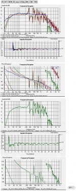
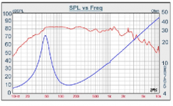
I am not a crossover expert, but it looks to me that the F one has a smoother response to work with. In fact, if you can eliminate that peak at 2,400 Hz, you have something approximating a natural 6dB/octave rolloff.
Hi,
I believe that the 'SM' version too can be LR2 XO'd at ~2 kHz:
b
")
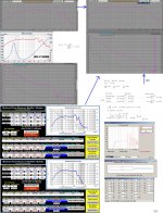
Attachments
9.25mm, and I don't think it's P-P. Looks like a 5mm gap and 23.6mm coil. I would imagine the spider is causing some problems by that point, though. Also from the drawings, looks xlim=xmax, so it would be a hard limit even if the spider could get all the way there.The excursion is listed at 9.5mm-I assume that is one way, (P-P). The chart applies to midpoint-to-peak excursion, so we divide that by half. That is about 5mm-about 0.2in. Still a very good excursion for that size speaker.
Last edited:
Where did you manage to find that voice coil length spec? I looked at parts express and at Tangband's own website, where I found the air gap of 5 mm but not the VcL.
http://www.tb-speaker.com/detail/1208_03/w5-1138sm.htm
I just assumed it was peak-to-peak because usually when they only give the excursion spec without mentioning it was one-way excursion, it's peak-to-peak. I'm not doubting you, I'm just curious where to find the spec.
http://www.tb-speaker.com/detail/1208_03/w5-1138sm.htm
I just assumed it was peak-to-peak because usually when they only give the excursion spec without mentioning it was one-way excursion, it's peak-to-peak. I'm not doubting you, I'm just curious where to find the spec.
I just assumed it was peak-to-peak because usually when they only give the excursion spec without mentioning it was one-way excursion, it's peak-to-peak.
"Usually" when Xmax is given, it is the one way excursion, as it is defined
.A speaker with an Xmax of 9.25mm should have linear response of 18.5mm peak to peak.
Xlim is often quoted as peak to peak, to make it seem even larger, especially when it is near Xmax.
I didn't. I thought that 4.6mm was not enough to justify that humongous surround (TB has smaller drivers with 5mm (10mm P-P) xmax and appropriately-sized surrounds so they don't do it just for fun), so I looked at the sheet, saw the 5mm air gap, meaning 23.6mm coil if the 9.25 xmax is to work out. So then I looked at the diagram to see whether it looked like there was room for a 23.6mm VC, and I thought it did look like there was room. That's all.Where did you manage to find that voice coil length spec? I looked at parts express and at Tangband's own website, where I found the air gap of 5 mm but not the VcL.
Also, I'm confused that you think of "one-way" and P-P as the same thing. To me, P-P means it has to go up, and then down, i.e. "both ways". Just sayin'... Actually I'm pretty sure I've seen "one way" on spec sheets when I know they mean zero-to-one-peak. Edit, oh wait, your first comment about it used it that way and then you went to the way I'm using it now.. Communication is hard.
Last edited:
"Usually" when Xmax is given, it is the one way excursion, as it is defined
A speaker with an Xmax of 9.25mm should have linear response of 18.5mm peak to peak.
It should be that way, but too often I've seen peak-to-peak excursion given as the spec.
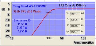
When I first went to select the box volume, I just used the formulas for the W5-1138SMF;
Vb => in ft^3
Vb = (4.1)(Vas)(Qt^2) = 4.748
Vb = 15 Vas (Qts^2.87) = .329
Vb=20*Vas*Qts^3.3 = .323
Vb = (Vas)/((Fb/Fs)^ (1/.31) ) = 0.172
Vb = ((Vas)/(((Qtc)/(Qts))2))-1 = 0.1633
Recomended by Parts Express = .26, * Enclosure volume/F3s based on BassBox "optimum" calculations
and every program gave a different volume also.
I liked .25
Question #1 Will a Vb of .25ft^3 and an fb of 38hz cause xmas limiting? not sure what you decided on, 3.2 or 6.4 for Vd?
Second question. designing a LR2 crossover using;
Linkwitz-Riley 2:
C1 = 0.0796/(RHf)
C2 = 0.0796/(RLf)
L1 = 0.3183RH/f
L2 = 0.3183RL/f
Q#2 do I use the impedance curve where it crosses the crossover point, 1.5K or 2K(have not decided). The sub-woofer looks like breakup above 1K so thinking about lower is better.
Q#3 or Should I use a RC in parallel to flatten the impedance.
Last edited:
Basically it all means that the excursion of the woofer is up to twice as long as I have been figuring, so it's SPL output is up to 6 dB higher than what I have been telling you.Wow there is a lot here, thanks. it may take me a bit to understand.
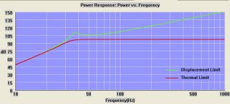
Instead of pumping out 90 or 92 dB at the lowest frequency at full power, it pumps out 96 or 98 dB before it hits the end of it's linear excursion.
Generally the figures I have been giving you for linear excursion is low distortion. When a speaker leaves it's linear excursion distortion goes up dramatically.
If you go back to posts #25 and 26, just change the amount of air you move from 2.9in³ to 5.8in³. The chart in post #25 has a line for 6.4in³, close enough. You will see that if you put this into a reflex box and tune to 30 Hz, you can get 90dB out of it before you run out of linear excursion.
If you put it in a box tuned to 45 Hz, you can drive it up to 98dB or so.
You're not going to be able to get a right size box to go down to 30 Hz, in my opinion you are much better off making the internal volume = Vas = 0.21ft³ and tuning to 45 Hz. But it is up to you.
Just to show my ignorance! If there is a difficulty with this speaker at higher frequencies in a two way could it be a good one for the speaker that Dave, Planet 10, often suggests : Fostex FF85K? Would it be easier to crossover to this?
jamikl
Hi Jamikl,
Agree, This would be a great idea. For the moment I'm not at my ordinary desktop, but within a week or so I can show a complete simulation using the Fostex XO'd at a frequency corresponding to Lamda/4 C-C distance.
b
My original goals for the speakers for the Grand-kids were:
A small Speaker about 10 X 7, now 11.5 X 7.25
Low distortion, up to 92 db SPL, thanks to you folks
Bass down to 30 Hz, now 33 Hz
Both drivers for $50, Now $56
Cannot wait to hear them.
Still do not know about the crossover beyond an LR2 and maybe a 6 db attenuation of the tweeter, 16 ohm R in series. When is the Impedance flatting RC network in parallel needed?
Attachments
When using a speaker like the one you have chosen that has nearly a 3/1 impedance rise in the crossover bandpass region, impedance compensation might be consideredWhen is the Impedance flatting RC network in parallel needed?
.Juggling the C/L values may be enough to avoid impedance compensation, but the 10 dB frequency response variation around 2K would be a bugger to try to fix even with a crossover as low as 1000 Hz.
I'd be looking for a very small "full range" speaker rather than a "tweeter" to go with the 5" "subwoofer" to get the crossover down to around 400-500 Hz.
Attachments
- Status
- This old topic is closed. If you want to reopen this topic, contact a moderator using the "Report Post" button.
- Home
- Loudspeakers
- Multi-Way
- 30 HZ from a 10 X 7 box