Yes, it seems to be a slightly similar design, except that in the A35 the chambers are separated by a kind of cloth-damped slot.
http://p10hifi.net/TLS/classics/images/dyna-A35-plans.gif
Maybe this damped tube approach might be more useful for those mid-woofers with higher Qts value to reduce the pronounced mid-bass response. This Peerless woofer has Qts value of 0,44. It seems like there might not be much advantage in using this kind of double-chamber enclosure with this particular Peerless unit.
This is basically the Dynaco A35 enclosure.
yup
 a simple resistive port
It's not slightly similar - it's the same. Aside from the specific volumes and tunings, etc., the resistive slot is equivalent to your "20x4 cm cardboard tube stuffed lightly with poly wadding from both ends". A port with some stuff in it is a port with some stuff in itYes, it seems to be a slightly similar design, except that in the A35 the chambers are separated by a kind of cloth-damped slot.
") . As for when this type of cabinet would be best, I don't know. I suppose you could look for measurements of impedance, bass response, and driver parameters from an A35 and see what it looks like the benefit was there.
. As for when this type of cabinet would be best, I don't know. I suppose you could look for measurements of impedance, bass response, and driver parameters from an A35 and see what it looks like the benefit was there.It's not slightly similar - it's the same. Aside from the specific volumes and tunings, etc., the resistive slot is equivalent to your "20x4 cm cardboard tube stuffed lightly with poly wadding from both ends". A port with some stuff in it is a port with some stuff in it
Wouldn't you say that a resistive slot is a type of controlling device very different from the damped resonance of a vented system? Of course what the OP is working with is a different type of vented system as the exit of the port is to a second chamber. I don't understand the meaning of "A port with some stuff in it is a port with some stuff in it".
Thanks for your advice. This time I placed the microphone exactly 3 mm away from the dust cup and set the sine wave volume in such a way that the dB meter reading was exactly 100 dB at 200 Hz frequency.
The first chart shows the frequency response in a cabinet with a 40x4 cm cardboard tube that was lightly stuffed from one end.
The second chart shows the frequency response in a 34L sealed cabinet.
The data shows decreased sound pressure level around 44-88 Hz area in the "vented" cabinet, while there seems to be a very slight level increase in the 14-34 Hz area. 100-120 Hz output is also higher in the vented cabinet.
Dynaco, shmynaco, back to the experiment...
Which impedance curve corresponds to which response curve?
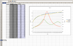
Wow - the green line looks like a classic bass reflex Z curve and the yellow line spl dip corresponds with the maximum driver damping from the tuned box. If the port were vented to the outside air, the dip would be a gain in overall spl. Instead the energy is dissipated inside the cabinet.
Nice experiment !
Nice experiment !
Last edited:
Unfortunately I can't think of any way of measuring that accurately. Not sure what kind of measurement system that would require. Of course I could do a visual examination, but that might not be very useful.Lets see cone displacement.
Your software doesn't model this?
Another way (old school) is to make a wedge.Q29 - How do you measure cone excursion of a driver?
This is tedious at best, but does work, just watch that Xmax and that dreadful Xlim!
Another way (old school) is to make a wedge.Q29 - How do you measure cone excursion of a driver?
This is tedious at best, but does work, just watch that Xmax and that dreadful Xlim!
I checked the link and it seems a nice way to measure the displacement.

But of course it doesn't take the resistive tube divider panel into account. So the actual result may be slightly different than this simulation! I might measure this if I have some time.
Well, if I use WinISD software to simulate this woofer in a 34L sealed enclosure, the cone excursion graph looks like this:Your software doesn't model this?
But of course it doesn't take the resistive tube divider panel into account. So the actual result may be slightly different than this simulation! I might measure this if I have some time.
Some Excel formulas for you...
Calculating excursion change is easy with a sealed enclosure because the driver is the only spl source:
Excursion change where db change = (db new - db reference)
=10^(db change/20)
Excursion change with frequency where (f reference)/(f new)
=(fₒ/f)^2
Excursion change with db and frequency:
=(10^(db change/20)) * (fₒ/f)^2
The A35 I mentioned has a slot with material added to make it resistive, and the slot exits into a second sealed chamber. The OP has the same thing, except the slot with some stuff in it is a tube with some stuff in it, which is equivalent.Wouldn't you say that a resistive slot is a type of controlling device very different from the damped resonance of a vented system? Of course what the OP is working with is a different type of vented system as the exit of the port is to a second chamber. I don't understand the meaning of "A port with some stuff in it is a port with some stuff in it".
My whole reason for saying so, though, was simply to point out that they thought it was a useful scheme in that case, so it would make sense to compare (if the data is out there) how and why the A35 cabinet+woofer functioned to what is going on here.
The image with the holey-panel in the OP reminded me of the Briggs "filter" reflex:
Adding damping material to either the above scheme or a pipe is indeed like the A35.
IG
An externally hosted image should be here but it was not working when we last tested it.
Adding damping material to either the above scheme or a pipe is indeed like the A35.
IG
Have you run across any good explanations for how the special damping of the A35 operates? What does "aperiodic" in connection with the A35 mean? An illustration of dual chamber aperiodic of the A35, by Gregg Dunn, shows a smallish slot with a panel thickness depth between the two chambers. The dimensions of the slot suggest to me that the Helmholtz resonance frequency of the slot and the volumes is above the bass range. Further then, it would seem that the vent is a resistive connection between the two enclosed volumes.The A35 I mentioned has a slot with material added to make it resistive, and the slot exits into a second sealed chamber. The OP has the same thing, except the slot with some stuff in it is a tube with some stuff in it, which is equivalent.
My whole reason for saying so, though, was simply to point out that they thought it was a useful scheme in that case, so it would make sense to compare (if the data is out there) how and why the A35 cabinet+woofer functioned to what is going on here.
The ones I looked at used fiber glass wrapped in linen or a linen pad with a layer of fiberglass ontop. This laid on a wire screen of about ¼" mesh stapled above a simple cutout in a ½" thick divider interior to the upper enclosure. Pad thickness wasn't much, a ¼" perhaps
Works similar to a double chamber bass reflex. Drivers with a higher FS seemed to benefit most
Works similar to a double chamber bass reflex. Drivers with a higher FS seemed to benefit most
I do not, and I don't even know if it is that special. Just suggesting something to research.Have you run across any good explanations for how the special damping of the A35 operates?
Mmmm, maybe but I doubt it. When you shrink the cross section, it allows you to make the vent shorter for a given resonance.What does "aperiodic" in connection with the A35 mean? An illustration of dual chamber aperiodic of the A35, by Gregg Dunn, shows a smallish slot with a panel thickness depth between the two chambers. The dimensions of the slot suggest to me that the Helmholtz resonance frequency of the slot and the volumes is above the bass range.
- Status
- This old topic is closed. If you want to reopen this topic, contact a moderator using the "Report Post" button.
- Home
- Loudspeakers
- Multi-Way
- Sealed enclosure experiment