Hello all,
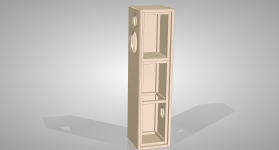
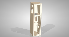
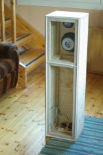
I am interested in this kind of loudspeaker enclosure design shown in the attachment. What are the pros/cons of this sort of loudspeaker cabinet?
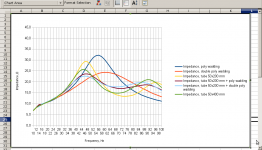
I built a prototype enclosure with detachable divider panel between the chambers so that I could make experiments. The woofer used was a 6½" unit from Peerless' old CSX-series (free-air resonance: 37 Hz). I measured the impedance of the loudspeaker with different divider panel configurations.
With the divider removed, the cabinet acts like a 34-litre sealed enclosure. There was an impedance peak around 56 Hz (42 Ω).
With a solid wood divider in place, the cabinet acts like a 12-litre sealed enclosure. The impedance peak was moved to around 74 Hz (35 Ω).
With some wadding in the divider panel the impedance peak rose to around 60 Hz (32 Ω).
I also tried placing stuffed 50x200mm and unstuffed 50x400mm cardboard tubes into the divider. It moved the impedance peak to a lower frequency, around 46-47 Hz (23 Ω) for the 200mm tube and 45 Hz (22 Ω) for the 400mm one.
It it beneficial anyway to lower the system resonance frequency in this way?
I am interested in this kind of loudspeaker enclosure design shown in the attachment. What are the pros/cons of this sort of loudspeaker cabinet?
I built a prototype enclosure with detachable divider panel between the chambers so that I could make experiments. The woofer used was a 6½" unit from Peerless' old CSX-series (free-air resonance: 37 Hz). I measured the impedance of the loudspeaker with different divider panel configurations.
With the divider removed, the cabinet acts like a 34-litre sealed enclosure. There was an impedance peak around 56 Hz (42 Ω).
With a solid wood divider in place, the cabinet acts like a 12-litre sealed enclosure. The impedance peak was moved to around 74 Hz (35 Ω).
With some wadding in the divider panel the impedance peak rose to around 60 Hz (32 Ω).
I also tried placing stuffed 50x200mm and unstuffed 50x400mm cardboard tubes into the divider. It moved the impedance peak to a lower frequency, around 46-47 Hz (23 Ω) for the 200mm tube and 45 Hz (22 Ω) for the 400mm one.
It it beneficial anyway to lower the system resonance frequency in this way?
Attachments
Last edited:
Hi, well it's good to experiment, best way to learn ")
Looks like a KEF design from the 80's
It depends, if it works, it works !
If you use a design program, you can play around with All the various parameters to your hearts desire & see what makes a difference etc
I recommmend WinISD http://www.linearteam.org/download/winisd-07x.exe & HornResponse http://www.diyaudio.com/forums/subwoofers/119854-hornresp.html
Looks like a KEF design from the 80's
It it beneficial anyway to lower the system resonance frequency in this way?
It depends, if it works, it works !
If you use a design program, you can play around with All the various parameters to your hearts desire & see what makes a difference etc
I recommmend WinISD http://www.linearteam.org/download/winisd-07x.exe & HornResponse http://www.diyaudio.com/forums/subwoofers/119854-hornresp.html
In your photos, what is the hole in the lower chamber at the back? Is that left open to the outside when you took your measurements?
The fact that the impedance peak is reduced when a cardboard tube is inserted into the divider suggests that Helmholtz resonance is occurring.
If your system is in fact sealed, then I believe that there would be a dip of SPL at the resonance frequency since your vent (the cardboard tube) connects the top chamber to the lower chamber only.
Regards,
Pete
Sorry, I forgot to mention that the hole on the back side panel is for the connection terminal. So it stays always closed.In your photos, what is the hole in the lower chamber at the back? Is that left open to the outside when you took your measurements?
Unfortunately I don't have any way to measure the frequency response of the system. At the university where I am studying and working we have a couple of Rion NL-20 and NL-22 sound pressure level meters. Those are used for measuring the SPL levels of concerts. Could those be used for hi-fi measurements too?
Rion Sound Level Meter NL-20 - Rion Sound Level Meter NL-20 Exporter, Importer, Manufacturer, Service Provider, Distributor, Supplier, Trading Company, Mumbai, India
Yes, I agree that experimentation is very interesting.Zero D
Actually I already modeled the sealed enclosure with WinISD Pro and found out that the simulated results do not differ much from my measurements.
You could measure the impedance versus frequency characteristic around the box resonance frequency. The shape of that curve would tell you whether or not you have devised a helmholtz resonator.
If helmholtz resonance is occurring, maybe you could use the damping effect of that resonance to counteract what otherwise would be a high Q such as 2.0 of the system with a solid wood divider?
Regards,
Pete
If helmholtz resonance is occurring, maybe you could use the damping effect of that resonance to counteract what otherwise would be a high Q such as 2.0 of the system with a solid wood divider?
Regards,
Pete
Dynaudio used to use a similar enclosure to damp its drivers, which had an overly high Qts and bass bump. They also employed a resistive port they called a Variovent. Despite their lofty claims of improving bass clarity, they were just a Band-Aid for boomy bass.
(I don't want to sound like I'm completely dissing Dynaudio, because they make some of the nicest drivers from the midbass up.)
Anyway, the point I'm trying to make is...
The more resistance you add to a bass reflex box, the higher your F3 regardless of any change of Fs. Any time you cause the sound energy from the driver to be consumed by fiber damping instead of by the damping effect of moving air and creating sound, you are throwing away some of the driver's efficiency at that frequency.
Damping material should only be added sparingly to the well-braced cabinet walls to reduce mid frequency standing waves. If you want the lowest f3, it would be difficult to beat Don Keele's formula, which yields a box 1.3 cubic feet, 34.1 hz port and 32.2 hz F3 for your driver.
http://www.xlrtechs.com/dbkeele.com/PDF/Keele%20(1972-05%20AES%20Preprint)%20-%20Vented%20Loudspeaker%20A%20Restatement.pdf
Last edited:
Unfortunately I don't have any way to measure the frequency response of the system. At the university where I am studying and working we have a couple of Rion NL-20 and NL-22 sound pressure level meters. Those are used for measuring the SPL levels of concerts. Could those be used for hi-fi measurements too?
That sound level meter looks like it might be okay to measure frequency response. To measure the frequency response around the system resonance frequency (bass range) you could put the mike element of the meter as close as possible to the dust cover of the woofer without actually touching the dust cover. This is called nearfield measurement and it eliminates any effect on the response from room reflections.
Sorry I missed that in your first post you provide an impedance versus frequency graph. The tube in the panel definitely results in Helmholtz resonance.
It is generally desirable to lower the resonance frequency, but that is usually in the context of the size of the system. It would seem unlikely that the technique could yield a good ratio of bass cut-off frequency and corresponding size of the box. See 4Torr's post on the system devised by Keele.
Regards,
Pete
Dynaudio used to use a similar enclosure to damp its drivers, which had an overly high Qts and bass bump. They also employed a resistive port they called a Variovent. Despite their lofty claims of improving bass clarity, they were just a Band-Aid for boomy bass.
It would seem that maybe with such a system as the OP put together you could combine the lower box resonance frequency of a bass-reflex system with the more gradual roll-off of a sealed system below resonance. That is, at frequencies below the Helmholtz resonance frequency, the vent is just a passageway between the upper and lower chambers. Knowing how to go about it to get a good result wouldn't be easy I'm sure.
It would seem that maybe with such a system as the OP put together you could combine the lower box resonance frequency of a bass-reflex system with the more gradual roll-off of a sealed system below resonance. That is, at frequencies below the Helmholtz resonance frequency, the vent is just a passageway between the upper and lower chambers. Knowing how to go about it to get a good result wouldn't be easy I'm sure.
When the tuned lower cabinet is off resonance and breathing in phase with the driver, both upper and lower cabinets are effectively joined and the response is similar to a sealed box. When the lower box and port are resonating however, they are operating in anti-phase with the driver and cancel each other at the mouth of the port. The upper chamber becomes the only compliance and sets the high pass slope. The result is more mid-bass efficiency and less low bass output.
The genius of a bass reflex is that the woofer, resonating chamber and port are arranged so that the front of the woofer and port output are in phase at chamber resonance. Driver excursion is reduced and sound pressure is optimally transferred to the surrounding air.
Last edited:
4Torr,
Is that pitting a high mass, low Qts, low Fs driver against a low mass, High Qts, high Fs, driver in such an enclosure?
Have considered doing the same as an experiment but instead of a dampening plate aka resistive port between the upper and lower, using an additional identical bass or midbass and using the current from the VC as a variable brake. Haven't done tho, thinking the phase shift induced would cause unwanted effects
I've been away for a while and it's nice to see that my experiment sparked up some discussion.
Here is a picture of the test setup.
Niiiice ! The plywood is so lousy here in California.
Sorry, I forgot to mention that the hole on the back side panel is for the connection terminal. So it stays always closed.
Unfortunately I don't have any way to measure the frequency response of the system. At the university where I am studying and working we have a couple of Rion NL-20 and NL-22 sound pressure level meters. Those are used for measuring the SPL levels of concerts. Could those be used for hi-fi measurements too?
Rion Sound Level Meter NL-20 - Rion Sound Level Meter NL-20 Exporter, Importer, Manufacturer, Service Provider, Distributor, Supplier, Trading Company, Mumbai, India
Yes, you can test the frequency response with a sine wave generator and close miking the driver a few centimeters away. This technique should be accurate below 400 hz or so and you can compare curves if you use the same reference level in the high midbass. Better yet, set your reference with a voltmeter at the input terminals at a given frequency. The results should be very interesting.
Yes, you can test the frequency response with a sine wave generator and close miking the driver a few centimeters away. This technique should be accurate below 400 hz or so and you can compare curves if you use the same reference level in the high midbass. Better yet, set your reference with a voltmeter at the input terminals at a given frequency. The results should be very interesting.
I forgot to add that you will need to put a low output impedance amplifier between the signal generator and the driver.
I also tried placing stuffed 50x200mm and unstuffed 50x400mm cardboard tubes into the divider. It moved the impedance peak to a lower frequency, around 46-47 Hz (23 Ω) for the 200mm tube and 45 Hz (22 Ω) for the 400mm one.
It it beneficial anyway to lower the system resonance frequency in this way?
Actually inserting the cardboard tubes raises or increases the system resonance frequency, if you consider the type of system that you have as being a type of modified vented system. The Helmholtz resonance frequency is a frequency somewhere in the valley between the pair of impedance peaks. So with the 50 X 200mm tube without wadding in place, Fb equals about 74 Hz. With the 50 X 400mm tube without wadding in place, Fb equals about 70 Hz.
As in your system the vent is subtracting from the acoustic output power of the system, it may be that frequency response won't drop off until below the frequency of the lower impedance peak, but I don't think that that is a foregone conclusion.
With the solid wooden divider in place, what is Qtc of the sealed system? If that Qtc is fairly high, say around 1.5, I think that you might have something quite good, but I think the fairly high Qtc is pretty necessary.
Anyway, if you can make some frequency response measurements, those would be interesting to see.
Regards,
Pete
This might be a good learning experience, but it does not hold much hope as a "new" enclosure type that has any advantages. At best it can be used to damp the woofer (damping material and a larger magnet are much more efficient ways to do this.) but at worst in will put a big hole in the response. Bose has used this idea for years, but eventually even they just eliminated it.
This might be a good learning experience, but it does not hold much hope as a "new" enclosure type that has any advantages. At best it can be used to damp the woofer (damping material and a larger magnet are much more efficient ways to do this.) but at worst in will put a big hole in the response. Bose has used this idea for years, but eventually even they just eliminated it.
Same conclusion I was thinking. Sims showed increased BL and or isobarik configurations worked better at dampening the extreme low end andor dampening material for midbass/midrange.
Have some 6.5" drivers that if AS would be a 0.5cu' and if BR 1.5cu' where I was running sims, Both are optimal. Having read something eons ago about placing a restrictor plate @ 1/3 volume. Think it was some old AR design from back in the 70's.
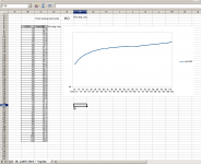
I finished the first frequency response measurement. This one is for the 20x4 cm cardboard tube stuffed lightly with poly wadding from both ends. The measurement device was set to measure ten seconds and the microphone was about 5 cm away from the woofer cone. Weighting was set to FLAT (other options were A-weighting and C-weighting).
I used sine wave for measurements, 2 Hz increments from 10..100 Hz. And 10 Hz increments from 100..120. Hz
Unfortunately I didn't know how to set the logarithmic Y-axis 'tick marks' to the f/Leq chart in Libreoffice so it's a bit difficult to use.
I still need to measure the "non-ported" version for reference.
Attachments
I finished the first frequency response measurement. This one is for the 20x4 cm cardboard tube stuffed lightly with poly wadding from both ends. The measurement device was set to measure ten seconds and the microphone was about 5 cm away from the woofer cone. Weighting was set to FLAT (other options were A-weighting and C-weighting).
I used sine wave for measurements, 2 Hz increments from 10..100 Hz. And 10 Hz increments from 100..120. Hz
Unfortunately I didn't know how to set the logarithmic Y-axis 'tick marks' to the f/Leq chart in Libreoffice so it's a bit difficult to use.
I still need to measure the "non-ported" version for reference.
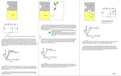
If you have the woofer radiating a continuous sine wave, then the microphone must be placed as close as possible to the cone (dust cover) of the woofer. If not, then presumably your measurements will be incorrect. If interested, see the article by D.B. Keele, Jr., "Low-Frequency Loudspeaker Assessment by Nearfield Sound-Pressure Measurement", April 1974 in the Journal of the Audio Engineering Society.
Maybe you could try placing the microphone about 3 mm away from the cone and see if you get different measurements.
The reference sound pressure level would be at about 200 Hz.
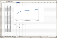
Thanks for your advice. This time I placed the microphone exactly 3 mm away from the dust cup and set the sine wave volume in such a way that the dB meter reading was exactly 100 dB at 200 Hz frequency.
The first chart shows the frequency response in a cabinet with a 40x4 cm cardboard tube that was lightly stuffed from one end.
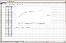
The second chart shows the frequency response in a 34L sealed cabinet.
The data shows decreased sound pressure level around 44-88 Hz area in the "vented" cabinet, while there seems to be a very slight level increase in the 14-34 Hz area. 100-120 Hz output is also higher in the vented cabinet.
The first chart shows the frequency response in a cabinet with a 40x4 cm cardboard tube that was lightly stuffed from one end.
The second chart shows the frequency response in a 34L sealed cabinet.
The data shows decreased sound pressure level around 44-88 Hz area in the "vented" cabinet, while there seems to be a very slight level increase in the 14-34 Hz area. 100-120 Hz output is also higher in the vented cabinet.
Attachments
- Status
- This old topic is closed. If you want to reopen this topic, contact a moderator using the "Report Post" button.
- Home
- Loudspeakers
- Multi-Way
- Sealed enclosure experiment