If this http://www.diyaudio.com/forums/attachments/multi-way/358275d1373039991-starting-active-open-baffle-design-minidsp-screen1.jpgI drug one of them outside this morning so I could get the MiniDSP set properly and the xml file saved so I could load it into the second one when it gets here.
Here's the result and what I did to get it. .... What do you guys think?
are your electrical correction filters, you basically got it wrong IMHO.

DrDyna, you just have become the victim of my sadistic urge to make things perfect. It’s not your fault – you just stood in the way.
Please let me explain why your approach is basically wrong. I will start with an EDGE sim of a 100x60 cm OB and a 15” driver centered at 27 cm from the bottom:

You can easily see how all dipole baffles start with a 6 dB acoustic high pass at low frequencies. Our example keeps this high pass to its dipole peak at 500 Hz (which is recognizable because the dipole dip at 1 kHz is clearly visible). It is very clear that the acoustic high pass will influence everything below 500 Hz.
Next simulation is for a real world Visaton BG 40 in this baffle:

It shows the 0, 30 and 60° response. You will notice how the real driver changes the response to a degree, but basically the baffle response rules. Note how the proportions of both diagrams are kept equal.
Next I have stretched the 0° response a bit along the x-axis to give room for the next filter variations:

I now consecutively applied a 6 dB electrical low pass at 50 Hz (black line) and an additional 12 dB electrical low pass at 100 Hz (red line). The non-EQ response is dashed:

Note how the acoustic high pass below 50 Hz is almost unchanged – it is almost 12 dB!
Note how the 6 dB electrical low pass not only straightens out the response (you can easily imagine to equalize it with some parametric EQs into the green range). It applies a falling acoustic response curve at the upper end of the woofer range too. Same for the 12 dB electrical low pass. Its influence at the lower end is small, but it works full tilt as a response leveler around 100 Hz and a cut-off above 100 Hz. Effectively nobody applied a real electrical low pass at 200 Hz, but we have got a working acoustical 20 dB low pass above 200 Hz.
Things get even worse when you install a passive EQ:

You remember the black dashed line? The continuous black line is the passive response with the 12 dB electrical low pass shown in the picture. You achieve an amazing 24 dB acoustic high pass below 50 Hz and a comparatively decent acoustic 12 dB low pass above 300 Hz.
What do I want you to understand in all this mess? It is the wildly different approach to filter design you have to take with dipoles. Symmetrical electrical crossovers are wrong in almost every case. You need to shape the acoustical response for every driver range to the intended form before you should even think about the application of over-all filters.
In my own case I have implied parametric EQs for the individual drivers only – there is not a single EQ for the summed response!
Rudolf
If this diyAudioare your electrical correction filters, you basically got it wrong IMHO.
DrDyna, you just have become the victim of my sadistic urge to make things perfect. It’s not your fault – you just stood in the way.
Please let me explain why your approach is basically wrong. I will start with an EDGE sim of a 100x60 cm OB and a 15” driver centered at 27 cm from the bottom:
View attachment 358637
You can easily see how all dipole baffles start with a 6 dB acoustic high pass at low frequencies. Our example keeps this high pass to its dipole peak at 500 Hz (which is recognizable because the dipole dip at 1 kHz is clearly visible). It is very clear that the acoustic high pass will influence everything below 500 Hz.
Next simulation is for a real world Visaton BG 40 in this baffle:
View attachment 358638
It shows the 0, 30 and 60° response. You will notice how the real driver changes the response to a degree, but basically the baffle response rules. Note how the proportions of both diagrams are kept equal.
Next I have stretched the 0° response a bit along the x-axis to give room for the next filter variations:
View attachment 358639
I now consecutively applied a 6 dB electrical low pass at 50 Hz (black line) and an additional 12 dB electrical low pass at 100 Hz (red line). The non-EQ response is dashed:
View attachment 358640
Note how the acoustic high pass below 50 Hz is almost unchanged – it is almost 12 dB!
Note how the 6 dB electrical low pass not only straightens out the response (you can easily imagine to equalize it with some parametric EQs into the green range). It applies a falling acoustic response curve at the upper end of the woofer range too. Same for the 12 dB electrical low pass. Its influence at the lower end is small, but it works full tilt as a response leveler around 100 Hz and a cut-off above 100 Hz. Effectively nobody applied a real electrical low pass at 200 Hz, but we have got a working acoustical 20 dB low pass above 200 Hz.
Things get even worse when you install a passive EQ:
View attachment 358641
You remember the black dashed line? The continuous black line is the passive response with the 12 dB electrical low pass shown in the picture. You achieve an amazing 24 dB acoustic high pass below 50 Hz and a comparatively decent acoustic 12 dB low pass above 300 Hz.
What do I want you to understand in all this mess? It is the wildly different approach to filter design you have to take with dipoles. Symmetrical electrical crossovers are wrong in almost every case. You need to shape the acoustical response for every driver range to the intended form before you should even think about the application of over-all filters.
In my own case I have implied parametric EQs for the individual drivers only – there is not a single EQ for the summed response!
Rudolf
I'm really making an honest attempt to read and digest all of this, but it's probably going to take me some time to figure out what I should change.
What I did when I measured was to measure each driver (with the others turned off) with the crossover engaged, and EQ a flat response within each band that I was trying to get each driver to cover.
Right now, if I play only one driver (the woofers together, or the midrage or the tweeter) they play relatively flat in the range that I've chosen.
Is the idea that the ranges I've picked for each driver should be different so that they are more "symbiotic" with naturally occurring dipole peaks and dips, or is the idea that what I've done is completely incorrect?
I really want to get this right, it's a learning experience for me, and I appreciate the time you spend talking about this with me
Edit: attaching measurements of the individual drivers. (not level matched)
Attachments
Last edited:
Hi,
the individual curves of your drivers look decent enough - except a detail in the Neo response, which I will approach later. And the regions for each driver(s) are well choosen. I have no argument with them at all.
My curiosity is about the crossover regions, filter orders and phase relations mainly. Did you measure every two neighbouring regions together - in phase and one out of phase? It seems you are going with LR filters. Did you get the LR-typical 6 dB difference at the Xover frequency between single driver curves and summing curves? Deep notches for the inverted case?
Have you done off-axis measurements which you would show? What happened to the high-pass of the midrange driver? It doesn't work lower than -20 dB?
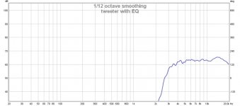
For the Neo3 I don't see any significant response dip at 7 kHz. This would be indicative for too much baffle area seen by the Neo3. Or did you apply some EQ there already? Which should not be done without parallel off-axis response control.
I hope that I don't come across too demanding or smart-alecky. Hopefully I'm only squeezing the best out of you.
Rudolf
the individual curves of your drivers look decent enough - except a detail in the Neo response, which I will approach later. And the regions for each driver(s) are well choosen. I have no argument with them at all.
My curiosity is about the crossover regions, filter orders and phase relations mainly. Did you measure every two neighbouring regions together - in phase and one out of phase? It seems you are going with LR filters. Did you get the LR-typical 6 dB difference at the Xover frequency between single driver curves and summing curves? Deep notches for the inverted case?
Have you done off-axis measurements which you would show? What happened to the high-pass of the midrange driver? It doesn't work lower than -20 dB?
For the Neo3 I don't see any significant response dip at 7 kHz. This would be indicative for too much baffle area seen by the Neo3. Or did you apply some EQ there already? Which should not be done without parallel off-axis response control.
I hope that I don't come across too demanding or smart-alecky.
Hopefully I'm only squeezing the best out of you. Rudolf
I'm not sure about the high pass on the mid, really I just picked where I wanted it to work and went with it. As far as summing, I didn't have to do too much, except for the midrange, which I applied a small amount of delay (0.15ms) and watched the dip in the response rise until it was where it looked good, then I stopped adding delay.Hi,
the individual curves of your drivers look decent enough - except a detail in the Neo response, which I will approach later. And the regions for each driver(s) are well choosen. I have no argument with them at all.
My curiosity is about the crossover regions, filter orders and phase relations mainly. Did you measure every two neighbouring regions together - in phase and one out of phase? It seems you are going with LR filters. Did you get the LR-typical 6 dB difference at the Xover frequency between single driver curves and summing curves? Deep notches for the inverted case?
Have you done off-axis measurements which you would show? What happened to the high-pass of the midrange driver? It doesn't work lower than -20 dB?
I do probably need to do more work, and that's what I'm looking for. I'm at a spot right now where it seems to be "ok", but I'm really looking for hints and tweaks to make it better.
For the Neo3 I don't see any significant response dip at 7 kHz. This would be indicative for too much baffle area seen by the Neo3. Or did you apply some EQ there already? Which should not be done without parallel off-axis response control.
The responses in the screenshots I posted are after EQ. They represent the chosen XO frequencies, (48db/oct, although I've been trying some 24). Some of it was quite peaky before EQ. I really try to do most of my EQ through subtraction, what I did was input the range of interest for each driver into REW and let it generate an EQ curve that gave me a reasonable response, then I added a little "flavor" or my own to the final EQ, such as a little dip around 6-7k to get rid of some sibilance. (that's not in the screenshots)
I hope that I don't come across too demanding or smart-alecky.
Rudolf
Oh, no no no, please...I can handle criticism, that's how these things get better! I will honestly try to absorb any information you give, and I will try as best I can to make a good attempt to make any corrections or implement any advice.
You won't hurt my feelings at all. <3 In fact, if I make major changes to anything, I keep all the xml files for the MiniDSP so that I can inspect them and try to learn through listening what each change means. I'm totally fine with having a minidsp-rudolf.xml
So far, any changes that I've made that were a result of feedback have been mostly positive, so, by all means...Give me sh*t!
Some observations of my Neo3. First a comparison of my equalized system (free hanging Neo3 on top from 2.5 kHz upward). On-axis measurement on tweeter height from 40 cm distance (top) and from listening position (bottom):then I added a little "flavor" or my own to the final EQ, such as a little dip around 6-7k to get rid of some sibilance. (that's not in the screenshots)
....
Give me sh*t!

You see how the 7 kHz dip gets more shallow with distance/reflections and off-axis. At 30° the response is quite smooth without any EQ:

Measurements are 0-90° at 10° intervals. 30° is pink.
If REW is trying to equalize that 6-8 kHz hole - don't allow it. This EQ will be a severe source of sibilance.
Listen to the response hole without thinking about the curve.
I had thought about raising it up high, I remember seeing the photo of when you measured yours and it was up on an ironing board
So, I guess it should be up for only the mid measurement? I remember Rudolf saying that the woofers should be near the ground, a concept I'm familiar with, which is why I left it where it was.
Out of curiosity, what sort of effect will measuring it like I did have on the mid?
Yes, the ironing board
Correct, only for midrange. Especially to find that pesky frequency, depth, and Q of that midrange dipole peak!
For tweeter, indoor with gating of 4-6ms is good enough.
For woofer, at under 100hz I don't think you can get any farfield useful, even raised 2m. I just do a nearfield (1-2cm at mouth), indoor.
Some observations of my Neo3. First a comparison of my equalized system (free hanging Neo3 on top from 2.5 kHz upward). On-axis measurement on tweeter height from 40 cm distance (top) and from listening position (bottom):
View attachment 358684
You see how the 7 kHz dip gets more shallow with distance/reflections and off-axis. At 30° the response is quite smooth without any EQ:
View attachment 358685
Measurements are 0-90° at 10° intervals. 30° is pink.
If REW is trying to equalize that 6-8 kHz hole - don't allow it. This EQ will be a severe source of sibilance.
Listen to the response hole without thinking about the curve.
Yeah, at first I allowed it to EQ the tweeter flat, but the sibilance drove me crazy..they were hissing at me! So I went into the DSP and started bypassing filters until the dip came back, and I even added a little more dip by creating a 1db drop from 6k to 7.5k. Now they just sparkle, and Eva Cassidy doesn't make me want to jump from the window
It would seem from your measurements though, I could actually just adjust the listening axis a few degrees and get the same effect. That is on the list of stuff to try today
I have a lazy susan downstairs, I'm going to try and do some off-axis measurements once the sun is fully up today.
gainphile said:Yes, the ironing board
Correct, only for midrange. Especially to find that pesky frequency, depth, and Q of that midrange dipole peak!
For tweeter, indoor with gating of 4-6ms is good enough.
For woofer, at under 100hz I don't think you can get any farfield useful, even raised 2m. I just do a nearfield (1-2cm at mouth), indoor.
Awesome, thanks. I'll see what types of measurements I can get today, and I also plan to try some other measuring software (tolvan) to see if it can tell me anything additional.
Edit: Rudolf, one other thing, do you have a version of your page that's in english? Google translate fails to translate it
Last edited:
Drdyna, based on my experience, you should use milder (12/24dB/oct) xo slopes. They come sort of naturally with dipoles and they help to mix drivers' polar responses more evenly.
When measuring outdoors - set the speaker on a stand and on grass to minimize "floor" reflection! 3-5' is good distance, IRgate 3ms for tweeter -9ms for mid-20ms for the low end of the mid or woofer section. Tell us what IRgate you used in the measuremnts that you show us. Generally for measuring the speaker alone - use short IR (3-12ms) and when checking/ eqing room response - use long gate (60-200ms)
Otherwise - keep going! About the tweeter - it's dispersion is important about how it sounds. I like mine when direct is flat and 15¤ response rolls off a little. But the amount/degree of this depens on your tweeter's type/characteristics (and your ears and room reflections).
Drdyna, based on my experience, you should use milder (12/24dB/oct) xo slopes. They come sort of naturally with dipoles and they help to mix drivers' polar responses more evenly.
I actually changed the slopes to 24db/oct yesterday, but I haven't measured it yet today. We shall see!
When measuring outdoors - set the speaker on a stand and on grass to minimize "floor" reflection! 3-5' is good distance, IRgate 3ms for tweeter -9ms for mid-20ms for the low end of the mid or woofer section. Tell us what IRgate you used in the measuremnts that you show us. Generally for measuring the speaker alone - use short IR (3-12ms) and when checking/ eqing room response - use long gate (60-200ms)
Otherwise - keep going! About the tweeter - it's dispersion is important about how it sounds. I like mine when direct is flat and 15¤ response rolls off a little. But the amount/degree of this depens on your tweeter's type/characteristics.
I'm hoping to be able to use Tolvan's Sirp today to do some gated measurements, I'm looking forward to what I can learn from it.
Hi Rudolf,
If I may slightly threadjack, on the other hand maybe it helps DrDyna as well.
Many thanks for the examples and explanation in post 121. My question is: do you recommend the application of the 6dB + 12dB filters at respectively 50Hz and 100Hz in real case as well, or did you only present it to show the impact/differences of the ‘acoustic’ and ‘electrical’ filters in dipole? I ask because I also read (more than once) your text ‘Open Baffle dipoles’ and based on section 4 (constant directivity) it looked to me that the ‘only’ equalization necessary is a 6dB/octave shelving low pass up to the 1st dipole peak (or before) and then something as a 24dB/octave LP Xover at the dipole peak frequency to cut out the non linear area – or am I thinking to easily?
On the other hand, I first thought that in the case of your example to DrDyna one loses a lot of sensitivity applying the filters at these low frequencies, but later I realized that the dB values of the lowest frequencies remain at the same level (they are not attenuated), and it are these low frequencies that determine the maximum output level obtainable from the driver (due to excursion limits), so ‘losing’ some dBs at higher frequencies is not very bad.
Thanks for your attention!
Erik
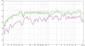
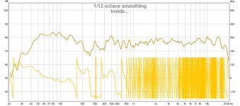
Now, inside the house, mic at mlp, both speakers playing..
(this sounds absolutely terrible.)
Edit: This upstairs room is horrible, and I'm going to be stuck up here for a few more months until the foundation is repaired and I can re-do my room downstairs, ahhh!
(this sounds absolutely terrible.)
Edit: This upstairs room is horrible, and I'm going to be stuck up here for a few more months until the foundation is repaired and I can re-do my room downstairs, ahhh!
Attachments
Last edited:
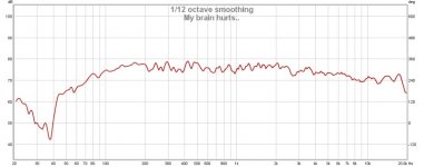
A little better now, but still sounds a bit hollow.
Edit...hm...maybe that recording was hollow...some aren't too bad at all. Maybe I should start a thread for music and recordings that are neutral or good for testing.
Edit...hm...maybe that recording was hollow...some aren't too bad at all. Maybe I should start a thread for music and recordings that are neutral or good for testing.
Attachments
Last edited:
Erik,My question is: do you recommend the application of the 6dB + 12dB filters at respectively 50Hz and 100Hz in real case as well, or did you only present it to show the impact/differences of the ‘acoustic’ and ‘electrical’ filters in dipole?
older digital processors like the Behringer DCX don't allow "cascading" low or high passes. You just have one filter stage for the high pass and one for the low pass. If you take a 6 dB/oct low pass at the bottom end of a driver to equalize the dipole loss, you don't have an additional low pass left to cut off at the upper end.
This made it mandatory to start with a shelf filter for dipole EQ:

Above is a 6 dB/oct shelf filter from 500-2000 Hz (blue line). You see, that it isn't steep enough to compensate the dipole roll-off (of the original red response curve) completely. What's more important: It doesn't do anything above 2 kHz - except the continuing 12 dB attenuation (green line) from 2 kHz up.
Wouldn't it be nice to have two cascading 6 dB/oct low pass filters instead:

Everything stays the same up to 2 kHz. But beyond that you get a steep roll-off. The attenuation numbers at 4 and 8 kHz are nearer to the truth than my crude rendering of the green curve. This cascading scheme will not work in all cases, but it might be more efficient in some.
Nice that you mention that. Most people get crazy if they see how dipole designs throw the efficiency away. But if it is still enough to drive the cone to Xmax at the lowest frequency, it is perfectly ok. The headroom will increase fast for all higher frequencies.On the other hand, I first thought that in the case of your example to DrDyna one loses a lot of sensitivity applying the filters at these low frequencies, but later I realized that ... it are these low frequencies that determine the maximum output level obtainable from the driver (due to excursion limits), so ‘losing’ some dBs at higher frequencies is not very bad.
Rudolf
Still listening to the result from post #135. It's growing on me. I'll call that one v1.2. It would seem that the only problems I have with it are on "some" recordings.
This dipole thing ..very clever. On one hand, it's very open sounding, and has tons of space. On the other hand, if you have a marginal recording...they tell you, right away.
This dipole thing ..very clever. On one hand, it's very open sounding, and has tons of space. On the other hand, if you have a marginal recording...they tell you, right away.
It does look bad - at least around 2 kHz.Doesn't look too bad.
I know that people like to show beautiful over-all response diagrams - but those don't tell the most important things about the rights and wrongs of the design. It would be more helpful to see the crossover regions for both drivers - summed and with opposite phase.
Providing a glimpse at your according REW/miniDSP EQ settings too would be most generous of you
Rudolf
It does look bad - at least around 2 kHz.
I know that people like to show beautiful over-all response diagrams - but those don't tell the most important things about the rights and wrongs of the design. It would be more helpful to see the crossover regions for both drivers - summed and with opposite phase.
Providing a glimpse at your according REW/miniDSP EQ settings too would be most generous of you
Rudolf
I'm actually in the process of redoing it again, the more I read the more I change.
And the more I'm not sure this baffle is going to do what I want.
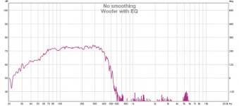
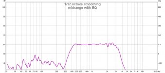
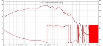
Example: This is what the woofer is doing with no filter and no eq.
Better: A little closer. Trying to get a good measurement so I can figure out a proper Linkwitz Transform.
Attachments
Last edited:
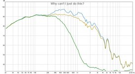
Is there a reason why I can't just EQ the peaks out of that without trying to use LT? The LT filter causes all kinds of EQ and waste below the frequency these are going to be playing anyway.
Edit: This...is there a reason why this is wrong?
Edit2: Top trace = No EQ No Filter. Middle trace EQ applied. Bottom trace EQ and 400 hz/24db/oct LPF applied.
Edit: This...is there a reason why this is wrong?
Edit2: Top trace = No EQ No Filter. Middle trace EQ applied. Bottom trace EQ and 400 hz/24db/oct LPF applied.
Attachments
Last edited:
- Status
- This old topic is closed. If you want to reopen this topic, contact a moderator using the "Report Post" button.
- Home
- Loudspeakers
- Multi-Way
- Starting an Active Open Baffle design.