the woofer measurement looks much more like what I would have expected ")
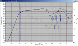
There is something odd with the tweeter measurement though... The impedance peak and the other irregularities in the impedance plot seem to have shifted up by about 1Khz. I wouldn't have thought that mounting it in the box should have had this effect...
could you do the tweeter one again just as a sanity check?
edit: Just out of interest, I've posted a comparison between a textbook 2nd order L/R at 3Khz with a textbook lpad (with 8db cut target) and what I had so far come up with. I think this is a good example of how poorly an off the shelf text book crossover can perform. text book is the black curve. Note this one has not got full bsc, as per Chris' comments. I'm not sure yet if it is as good or not. using full BSC gives a bit more room for manipulation
Tony.
Attachments
Last edited:
Hi Shaolin. I decided that as a sanity check I should check how much it would cost for the crossover components in the crossover I was modelling. The bad news is that it came to almost $100 (and that is not using anything expensive). Just off the shelf parts from parts express. I'm guessing that is many times the cost of the actual drivers, so may not make a lot of sense to persue.
I think you said originally you had some off the shelf crossovers?? Could you post what they actually are, ie rated ohms, and whether they are 2nd order 4th order and what the crossover frequency is?
Also if you could the values of the caps used in them....
It may be more economically sensible to approach it from a improve what you have got rather than start from scratch angle.
A large part of the cost was inductors. There were 4 and they were biggish values. three of them were 1mH or bigger.
I can post what I came up with but I'm just not sure it makes economic sense
Tony.
thanks my next question after looking at the crossover was is it a 10uF cap looks like textbook 1st order. so coil will be around 0.63mH (I'll guess the closest standard value).
I put this into speaker workshop this morning and it was surprisingly not too bad (better than the 2nd order 3Khz I modeled before).
I accidentally shut down my main machine (rather than the VM) and it is looking like the speaker workshop project I had for this has been corrupted running a checkdisk now hoping it will come back.
2Khz is a very low crossover point but I think that it should be possible to improve on your basic XO mainly concetrating on the peak from the woofer.
I think you said you had an LPAD. Is it one made from two resistors or one of the infinitely variable types. If two resistors, what value for the series and parallel ones..
Tony.
looks like textbook 1st order. so coil will be around 0.63mH (I'll guess the closest standard value). I put this into speaker workshop this morning and it was surprisingly not too bad (better than the 2nd order 3Khz I modeled before).
I accidentally shut down my main machine (rather than the VM) and it is looking like the speaker workshop project I had for this has been corrupted
running a checkdisk now hoping it will come back. 2Khz is a very low crossover point but I think that it should be possible to improve on your basic XO mainly concetrating on the peak from the woofer.
I think you said you had an LPAD. Is it one made from two resistors or one of the infinitely variable types. If two resistors, what value for the series and parallel ones..
Tony.
Heya,
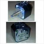
Here's the L-pad detail. It's an AT-50H, similar to this but the stereo variant:
L-Pad 50W Mono 1" Shaft 8 Ohm 260-255
At this point if the box isn't salvageable, I'm thinking of possibly building something like this with the dayton ND91:
The Sprite - self-contained ND90 boombox
I probably should have started with a kit in the first place
Thanks!
Attachments
Hi Shaolin,
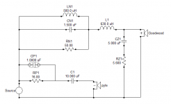
Below are the results of tweaking the off the shelf crossover circuit. The first is the actual modifications to the circuit.
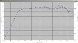
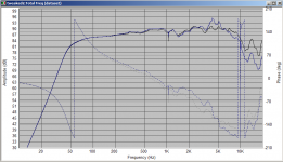
2nd is the simulated spl compared to the (blue) simulation of the off the shelf crossover with just an lpad. There isn't a huge difference, but I think the removal of the peak between 4 and 5Khz should make quite a difference to the sound balance.
3rd is the simulation with the tweeter phase reversed (note that it should be connected in reverse polarity in this crossover). The null is not too bad and shows reasonable phase tracking in the crossover region. The off the shelf doesn't do as well.
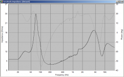
4th is the impedance plot to show that there are no nasty dips.
The crossover is actually 2nd order bessel acoustically at around 2Khz. This is rather low for this tweeter, but provided the speakers are not pushed too hard it will probably be ok.
The bass response was using the model for the bass reflex tuning of 53Hz in your existing enclosure. I'll see if I can do a sealed for comparison.
Note that this still needs some baffle step compensation. I'd suggest doing this as passive line level as Chris posted earlier. It should be much cheaper and easier and easier on your amp. Rod Elliot covers it here --> Baffle Step Compensation
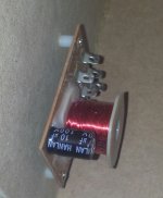
I haven't tallied up the cost for this variation, but I think the coils will be the most expensive and I simmed using these ones Jantzen 0.50mH 20 AWG Air Core Inductor 255-036 which are only $4.59 each. In total it probably won't be much over $20.
So I guess the question is whether you want to spend a bit more to see what improvments you can make or start from scratch with a proven design. I guess the most important thing is to have learned something from this one
Tony.
Below are the results of tweaking the off the shelf crossover circuit. The first is the actual modifications to the circuit.
2nd is the simulated spl compared to the (blue) simulation of the off the shelf crossover with just an lpad. There isn't a huge difference, but I think the removal of the peak between 4 and 5Khz should make quite a difference to the sound balance.
3rd is the simulation with the tweeter phase reversed (note that it should be connected in reverse polarity in this crossover). The null is not too bad and shows reasonable phase tracking in the crossover region. The off the shelf doesn't do as well.
4th is the impedance plot to show that there are no nasty dips.
The crossover is actually 2nd order bessel acoustically at around 2Khz. This is rather low for this tweeter, but provided the speakers are not pushed too hard it will probably be ok.
The bass response was using the model for the bass reflex tuning of 53Hz in your existing enclosure. I'll see if I can do a sealed for comparison.
Note that this still needs some baffle step compensation. I'd suggest doing this as passive line level as Chris posted earlier. It should be much cheaper and easier and easier on your amp. Rod Elliot covers it here --> Baffle Step Compensation
I haven't tallied up the cost for this variation, but I think the coils will be the most expensive and I simmed using these ones Jantzen 0.50mH 20 AWG Air Core Inductor 255-036 which are only $4.59 each. In total it probably won't be much over $20.
So I guess the question is whether you want to spend a bit more to see what improvments you can make or start from scratch with a proven design. I guess the most important thing is to have learned something from this one
Tony.
Attachments
Hi there,
First off, thanks again for taking the time to help me work through this.
I think I will give it a go and try the modifications you're suggesting. I'd much rather put it together and have it sound less than optimal than have the speakers sitting on a shelf mocking me till the end of my days.
Just a quick question - why is the 1000uf cap shown with a different symbol on the schematic?
I should have some more questions for you by the time I get to work.
Cheers
Hi Looks like I had just clicked on it (1uF cap), It shows up like that when selected in speaker workshop
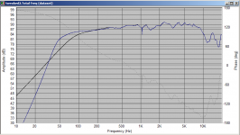
I've just done the sim with the sealed alignment (with baffle step factored in) and attached is the comparison to the vented. Blue is the vented.
Tony.
I've just done the sim with the sealed alignment (with baffle step factored in) and attached is the comparison to the vented. Blue is the vented.
Tony.
Attachments
First the rated bass response is 56hz, but the resonance of the speaker is about 65hz. Below resonance bass drops off quickly.
In a sealed cabinet, the rated low end is 69hz. That's just OK, but no more.
However, if a ported bass reflex cabinet, of about twice the size, the rated low end is 36hz.
In short, you don't get much bass in a sealed cabinet.
The next issue that other are addressing is the difference in the output of the drivers.
To determine this, look at the Sensitivity rating of both speaker -
88dB = Goldwood Woofer
100db = Pyle Tweeter.
That means you have to bring the level of the Pyle Tweeter down close to that of the Goldwood woofer.
I have a speaker that uses an off the shelf crossover, it is not perfect, but it works fine for a first time build.
Here are a couple of photos -
Notice the white rectangles behind the crossover. Those make up an L-Pad; one to bring the level of the Horn Tweeter down, and the other to bring the level of the Horn Midrange down.
On the next image -
You can see the crossover and the drivers completely wired. Notice the VARIABLE L-PAD, the white resistors being the Horn Midrange down the first step, then the variable L-Pad lets me adjust it the rest of the way to my taste. Cutting the level down on the Midrange with the resistors makes the L-Pad a bit less sensitive and gives me a finer adjustment. But, if I had know precisely how must attenuation I needed, I could have accomplished it with just fixed resistors.
At the very bottom of this link -
Crossover Design Chart and Inductance vs. Frequency Calculator(Low-pass)
You will find a Calculator that will give you the necessary resistor values to get any attenuation you want for any impedance of speaker.
This creates an Impedance Balanced attenuation. You have an 8 ohm tweeter, so no matter how great or slight the attenuation, the amp will always see 8 ohms there.
The resistors I'm using are 10 watt audio resistors, very low cost and easy to find.
In theory you would need this much attenuation -
At = St - Sb = 100 - 88 = 12 dB
But, what works in theory, doesn't always work in practice. I would calculate the resistor values for -9db, -12db, and -15db then try them all and see which you feel sound best.
The resistor are probably less than $2 each.
As an example -
Dayton Audio DNR-2.0 2 Ohm 10W Precision Audio Grade Resisto 004-2
The Shipping from Parts Express on small order can be pretty high, but these resistor are common as dirt and you can find them anywhere. Do a Google-Shopping search and see what comes up. Or call some local HiFi or Electronic stores.
I'm assuming these are bookshelf speaker, so I don't know who much room you have, but if you have a variable L-Pad, you can just dial in the what sounds best to you.
L-Pad 100W Mono 1" Shaft 8 Ohm 260-265
As you can see from this photo and my photo above these are not tiny.
So, if you want big deep bass, then use the Bass Reflex cabinet volume and make the box/port resonate at about 60hz. Though the precise resonance frequency it somewhat up for debate.
When you calculate to internal volume of the cabinet, you need to subtract the space used up by the woofer.
Measure the magnet, and calculate the volume of a cylinder.
Measure the cone from the center of the Surround to the center of the far side surround, then best guess the angle of the size and the height, and calculate the volume of a Cone.
Add the two and subtract it from the calculated volume of the cabinet. Then select the resonance frequency which is typically the resonance frequency of the Bass driver (Resonant Frequency (Fs)). Then find a port diameter and depth that will work in your cabinet.
Here is one easy to use port calculator -
LinearTeam - Port Calculator
For now, concentrate on getting the Tweeter down to the level of the Bass driver.
Then see where you stand.
That should get the ball rolling.
Steve
In a sealed cabinet, the rated low end is 69hz. That's just OK, but no more.
However, if a ported bass reflex cabinet, of about twice the size, the rated low end is 36hz.
In short, you don't get much bass in a sealed cabinet.
The next issue that other are addressing is the difference in the output of the drivers.
To determine this, look at the Sensitivity rating of both speaker -
88dB = Goldwood Woofer
100db = Pyle Tweeter.
That means you have to bring the level of the Pyle Tweeter down close to that of the Goldwood woofer.
I have a speaker that uses an off the shelf crossover, it is not perfect, but it works fine for a first time build.
Here are a couple of photos -
An externally hosted image should be here but it was not working when we last tested it.
Notice the white rectangles behind the crossover. Those make up an L-Pad; one to bring the level of the Horn Tweeter down, and the other to bring the level of the Horn Midrange down.
On the next image -
An externally hosted image should be here but it was not working when we last tested it.
You can see the crossover and the drivers completely wired. Notice the VARIABLE L-PAD, the white resistors being the Horn Midrange down the first step, then the variable L-Pad lets me adjust it the rest of the way to my taste. Cutting the level down on the Midrange with the resistors makes the L-Pad a bit less sensitive and gives me a finer adjustment. But, if I had know precisely how must attenuation I needed, I could have accomplished it with just fixed resistors.
At the very bottom of this link -
Crossover Design Chart and Inductance vs. Frequency Calculator(Low-pass)
You will find a Calculator that will give you the necessary resistor values to get any attenuation you want for any impedance of speaker.
This creates an Impedance Balanced attenuation. You have an 8 ohm tweeter, so no matter how great or slight the attenuation, the amp will always see 8 ohms there.
The resistors I'm using are 10 watt audio resistors, very low cost and easy to find.
In theory you would need this much attenuation -
At = St - Sb = 100 - 88 = 12 dB
But, what works in theory, doesn't always work in practice. I would calculate the resistor values for -9db, -12db, and -15db then try them all and see which you feel sound best.
The resistor are probably less than $2 each.
As an example -
Dayton Audio DNR-2.0 2 Ohm 10W Precision Audio Grade Resisto 004-2
The Shipping from Parts Express on small order can be pretty high, but these resistor are common as dirt and you can find them anywhere. Do a Google-Shopping search and see what comes up. Or call some local HiFi or Electronic stores.
I'm assuming these are bookshelf speaker, so I don't know who much room you have, but if you have a variable L-Pad, you can just dial in the what sounds best to you.
L-Pad 100W Mono 1" Shaft 8 Ohm 260-265
As you can see from this photo and my photo above these are not tiny.
So, if you want big deep bass, then use the Bass Reflex cabinet volume and make the box/port resonate at about 60hz. Though the precise resonance frequency it somewhat up for debate.
When you calculate to internal volume of the cabinet, you need to subtract the space used up by the woofer.
Measure the magnet, and calculate the volume of a cylinder.
Measure the cone from the center of the Surround to the center of the far side surround, then best guess the angle of the size and the height, and calculate the volume of a Cone.
Add the two and subtract it from the calculated volume of the cabinet. Then select the resonance frequency which is typically the resonance frequency of the Bass driver (Resonant Frequency (Fs)). Then find a port diameter and depth that will work in your cabinet.
Here is one easy to use port calculator -
LinearTeam - Port Calculator
For now, concentrate on getting the Tweeter down to the level of the Bass driver.
Then see where you stand.
That should get the ball rolling.
Steve
Last edited:
Hi The Rod elliot one goes *before* the amp. You can also do BSC in the crossover, but I think the passive line level before the amp in this case will be easier, cheaper and probably more effective
Tony.
I'm using a TA2024 with a soldered on stereo input. I'm removing the input and replacing it with a chassis mount...I'm guessing the BSC goes between the input and the board then?
TA2024 MKV Bluetooth Tripath Amplifier 2X 15 Watts 12V Fully Finished | eBay
Thanks -
That should get the ball rolling.
Steve
Thanks Steve -
I haven't tallied up the cost for this variation, but I think the coils will be the most expensive and I simmed using these ones Jantzen 0.50mH 20 AWG Air Core Inductor 255-036 which are only $4.59 each. In total it probably won't be much over $20.
Another quick question -
I'm sourcing from Solen here in Canada:
Solen Electronique Inc.
Looks like the inductors are available in 20 AWG and at 0.51mH. Is this okay? For the caps and resistors, what variants are the cheapest?
Thanks in advance.
- Status
- This old topic is closed. If you want to reopen this topic, contact a moderator using the "Report Post" button.
- Home
- Loudspeakers
- Multi-Way
- Help with bass response on my first build...