Surprisingly, Time Alignment is not to do with aligning voicecoils. ")
But in my experience, you need to set the tweeter back a BIT. I was lucky enough to study digital and analog filtering under the outrageously talented Prof. Tony Constantinides at Imperial College. Along with antenna Theory and the spatial Fourier transform under Doctor Clarke, which is diffraction theory at heart.
When you do it all right, and you will understand that I won't give it all away to the hopeless duffers in this ego-driven game and forum, you can get some outrageously good results with even average components.
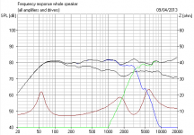
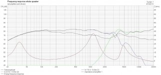
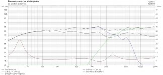
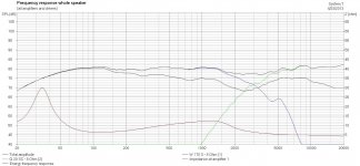
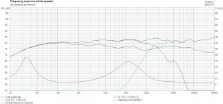
I mean, how good is this for a 6" woofer plus 1" tweeter two way? I don't make this up.
But in my experience, you need to set the tweeter back a BIT. I was lucky enough to study digital and analog filtering under the outrageously talented Prof. Tony Constantinides at Imperial College. Along with antenna Theory and the spatial Fourier transform under Doctor Clarke, which is diffraction theory at heart.
When you do it all right, and you will understand that I won't give it all away to the hopeless duffers in this ego-driven game and forum, you can get some outrageously good results with even average components.
I mean, how good is this for a 6" woofer plus 1" tweeter two way? I don't make this up.
Attachments
When you do it all right, and you will understand that I won't give it all away to the hopeless duffers in this ego-driven game and forum, you can get some outrageously good results with even average components.
I mean, how good is this for a 6" woofer plus 1" tweeter two way? I don't make this up.
You can tell me Steve (I am a hopeless duffer though..).
You can tell me Steve (I am a hopeless duffer though..).
Well , I'll give you a clue.
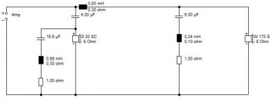
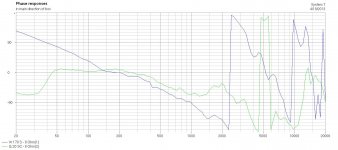
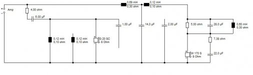
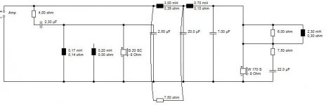
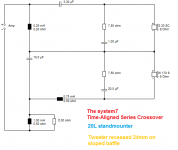
I used these and a bit of time alignment (2.5cms) and a seriously clever (IMO) but simple 9 element crossover.
W 170 S - 8 Ohm
G 20 SC - 8 Ohm
It's pure quantum mechanics at heart. Think double slit diffraction.
It's pure quantum mechanics at heart. Think double slit diffraction.
Hi Steve;
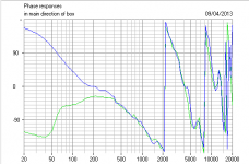
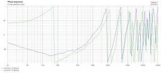
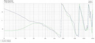
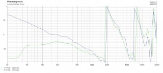
1st - that crossover phase alignment and frequency response is seriously sick!
2nd - HELP! I certainly don't have your pedigree in digital signal processing and diffraction, but I took your clue and tried combining various "resonators" in the forms of either series or parallel notch filters tuned at either 1.5, 3 or 6KHz in different configurations. Mostly I tried in conventional parallel driver set ups - but I also started trying a pseudo series driver set up and it is coming closer - but no way have I been able to capture all the nice aspects or your design or even come close! (worse than a hopeless duffer, if there is such a rank)
I'll put together separate postings showing what I tried - but any more clues you'd be willing to reveal? On the plus side your puzzle forced me to download and get to use boxsim and has also forced me to expand how I think about crossover networks beyond the traditional. On the down side - lots of head scratching!
Any more clues appreciated - it would be nice to actually build that thing!
Thanks - Paul
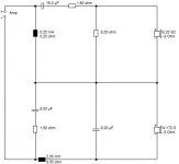
Here's one attempt - a 2nd O filter with some 3kHz notches in series -
Some hope at getting good phase alignment but the rest is pitiful:
Some hope at getting good phase alignment but the rest is pitiful:
Attachments
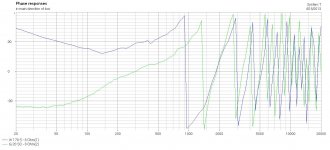
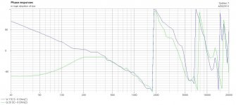
Here is an attempt to get the steeper rolloffs you have achieved by putting series notches in parallel - tuned at -1 octave for the tweet and + 1 octave for the woof:
(phase alignment not too bad near xover - but not over a broad freq range)
(phase alignment not too bad near xover - but not over a broad freq range)
Attachments
Here is an attempt to match those double impedance bumps + and - crossover in a pseudo series driver arrangement with some - resonators. Clearly I have no idea how to do this series driver stuff
Attachments
So Steve - am I remotely on the right continent with any of these approaches?
Any guidance is greatly appreciated.
This all started out trying to improve my very rudimentary understanding of crossovers by looking at what was out there and "taking them apart" to the extent I could with a SPICE simulator.
Now you have thrown out this awesome FR and Phase cure that has peaked my interest to be sure.
thx
Not really, you are making it too complicated.So Steve - am I remotely on the right continent with any of these approaches?
The discussions of serial crossovers have been a torment at this forum, and I've got quite cross with some people here. But they do something rather special that you can only approach with parallel filters. An ex radio-frequency engineer like myself spots it straightaway. Radio engineers do stuff PROPERLY!
I will tell you how filters work though. Firstly "diffraction" is in any cabinet, room and drive unit. It's even in the filter. It is a power response that looks like this:
An externally hosted image should be here but it was not working when we last tested it.
You will never get rid of it, so you must work with it. The envelope is a gaussian distribution, the wiggles and cancellations reflect the wavelength. The gaussian is, AFAIK, unique in signal processing, because it is its own inverse and that is why nature (and engineers who respect elegance in mathematics) uses it so much. When you get a gaussian response, you are doing something right.
The second diagram shows how linear phase filters and the impulse response works. Everybody in electrical engineering knows this one, but few really understand it.
An externally hosted image should be here but it was not working when we last tested it.
This is a thing of great loveliness. It is known as a SINC FUNCTION. It is also the Dirac Delta function of quantum mechanics. It tells you that if a filter is steep, it makes the signal ring for a long time. The reason people don't understand it, is that it's a bit of a theoretical thing, because real world filters are causal and assymetric in response. But the transform is straightforward enough and you have to accept that any real loudspeaker will have some group delay or time signature in its response.
FWIW, group delay is the SLOPE of the phase. It's a differential relation. So phase alignment is only part of it. You also want to keep the slope fairly flat.
Hope that helps. You might think you are doing loudspeakers, but actually it's the maths of Quantum Mechanics. Which is WAY COOL, IMO.
Not really, you are making it too complicated.
....
Hope that helps. You might think you are doing loudspeakers, but actually it's the maths of Quantum Mechanics. Which is WAY COOL, IMO.
Hmm - we might have two definitions of complicated
You know the old adage - "give a man a fish and you feed him for a day, teach him to fish and you feed him for a lifetime".... Well - with all due respect Steve I feel like your process of teaching is to describe the fish genome, the metallurgy of hook production and the organic chemistry of silk and nylon fiber production!(all while dangling a lovely fish in front of the student)
Technically I have no doubt it is fully correct and truly meaningful on some fundamental basis - but I wonder what % of those on this forum can actually make the linkage to practical crossover design?
It sure would be nice to describe your process of getting such nice phase matching and flat slope of phase change through frequency all the while maintaining flat SPL through frequency much in the way that Allen B put together a tutorial on designing crossovers without measurements.
In the mean time I hacked away at this in a more trial and error approach - starting with some LR 3rd and 4th order HP and LP filters, mixing and matching them, putting in Zoble networks and notch filters here and there, moving the tweeter z a bit back etc etc..
Can get a bit closer but still missing that nice sharp LP filter rolloff you have and a bit lumpy (a fish - but a bit of a stinker
)Thanks for pushing me on to say the least!
Attachments
When you finally get a grip on how nature works, you will find she always goes for the elegant solutions.
For instance, here's the five platonic solids that exist in 3D space. 4D space gets more interesting as it goes. There is a 6th solution.
I am being a hard taskmaster here, but you seem talented so I'll persevere. I really don't do crossover design for bricklayers. Waste of time.
Here's where I got to before being ripped to pieces by someone who I had clearly gone over the head of:
http://www.diyaudio.com/forums/multi-way/27969-series-crossover-16.html#post3436472
That was nearly there. It just needed Bafflestep. Then it all fits into place. You can lose the notches, just keep the Zobels.
That's all you get. You must work out the rest for yourself. But I will tell you where the natural point of crossover occurs:
Go for the geometric mean of the 1400Hz tweeter Fs and the 5kHz resonance of a 6.5" driver. Roughly.
An externally hosted image should be here but it was not working when we last tested it.
For instance, here's the five platonic solids that exist in 3D space. 4D space gets more interesting as it goes. There is a 6th solution.
I am being a hard taskmaster here, but you seem talented so I'll persevere. I really don't do crossover design for bricklayers. Waste of time.
Here's where I got to before being ripped to pieces by someone who I had clearly gone over the head of:
http://www.diyaudio.com/forums/multi-way/27969-series-crossover-16.html#post3436472
That was nearly there. It just needed Bafflestep. Then it all fits into place. You can lose the notches, just keep the Zobels.
That's all you get. You must work out the rest for yourself. But I will tell you where the natural point of crossover occurs:
Lynn Olson said:When working with rigid-cone drivers, there are some hard choices to make: if you lower the crossover frequency to minimize driver coloration, tweeter IM distortion skyrockets, resulting in raspy, distorted high frequencies at mid-to-high listening levels; if you raise the crossover frequency to improve the sound of the tweeter, the rigid-driver breakup creeps in, resulting in a forward, aggressive sound at moderate listening levels, and complete breakup at high levels. (Unlike paper cones, Kevlar, metal, and carbon fibers do not go into gradual breakup.) With the drivers we have today, the best all-around compromise is a 2nd, 3rd, or 4th-order (12-24dB/Oct.) crossover with an additional notch filter tuned to remove the most significant HF resonance of the midbass driver.
Go for the geometric mean of the 1400Hz tweeter Fs and the 5kHz resonance of a 6.5" driver. Roughly.
When you finally get a grip on how nature works, you will find she always goes for the elegant solutions.
An externally hosted image should be here but it was not working when we last tested it.
I really don't do crossover design for bricklayers. Waste of time.
Thanks for the vote of confidence - hope it is not misplaced
I too appreciate nature's beauty in math.
I have a love for the Fibonacci sequence and fractals and as I am sure you know the Platonic solids are intimately related to the Golden Ratio and thus the Fibonacci sequence. (I am sure you have probably read it - but if not Mario Livio's book is a good read) What this all has to do with crossover networks I haven't a clue yet, but will keep at it with your insightful albeit cryptic clues.
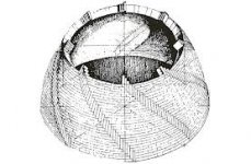
(Will be vacationing in Spain for a few weeks coming up so may be a while)Don't be so hard on bricklayers - Brunelleschi was a bricklayer at heart
(some very interesting brick designs were needed to accomplish the largest freestanding dome in the world)Cheers
Attachments

Ah, yes. It is good to take a break from a problem...the brain gets a rest and you come back refreshed and looking for even more symettry.
That circuit is OK as far as it goes, but I don't like the overall impedance or that damping resistor in the bass shunt arm, and it's just not quite pretty enough...
But your Phi (1.618....) is surely only a minor player in the universe. It is merely algebraic for one thing. I'm all for including it in speaker boxes and bricklaying, but that's about it.
The transcendentals are much more interesting, and it's surprising how few of them we actually use. Exponential e (2.718....) and Pi (3.14...whatever it is...LOL) are the backbone of our engineering maths. And as we have discovered, Quantum Mechanics, Information Theory and Loudspeakers use the same principles right down to the uncertainty principle relating energy to time.
An externally hosted image should be here but it was not working when we last tested it.
That circuit is OK as far as it goes, but I don't like the overall impedance or that damping resistor in the bass shunt arm, and it's just not quite pretty enough...
But your Phi (1.618....) is surely only a minor player in the universe. It is merely algebraic for one thing. I'm all for including it in speaker boxes and bricklaying, but that's about it.
The transcendentals are much more interesting, and it's surprising how few of them we actually use. Exponential e (2.718....) and Pi (3.14...whatever it is...LOL) are the backbone of our engineering maths. And as we have discovered, Quantum Mechanics, Information Theory and Loudspeakers use the same principles right down to the uncertainty principle relating energy to time.
Cantor confindently asserted that the transcendentals were in a vast majority to the algebraic numbers and did so without exhibiting a single conrete example of a transcendental number. Mathematical Historian Eric Temple Bell said of it, "The algebraic numbers are spotted over the plane like the stars against a black sky; the dense blackness is the firmament of the transcendentals."
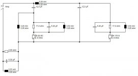
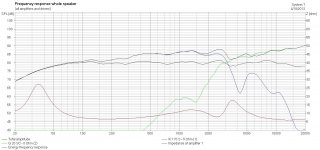
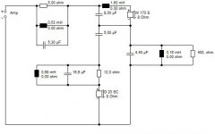
Normally the tweeter would play the loudest at very high frequencies. With the 2.2 ohm that end will be attenuated. The other resistor attenuates the shelf below the high end. The woofer is also affected by these resistors with capacitors, the way the curve of attenuation looks like. Less clean capacitance gives less lift for the woofer near the crossover point. The woofer probably has a nasty peak near the crossover point.
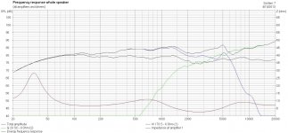
Damn you System 7 - I can just not get the Xover steep enough near the Xover point (and match the phase at the same time)! This is the best of several tries so far where I prioritized being down ~15dB at the 5KHz cone breakup and tried to be low on the HP filter for the tweet Fs at ~ 1400Hz. Almost buildable, though the lack of crisp filters leads to ~3dB sag in the middle. - not sure about that high frequency impedance - is that ok?  Also 2 more parts than you used -
Also 2 more parts than you used - Attachments
@strawberry: Bit hurt by your lack of faith there, my old fruit! You had it right the first time. It IS interesting. You who likes a bit of ripple in the old Chebyscheff filter.
@phivates: Don't go all sensitive on me. Irony is misunderstood by Americans. Why is that? Beats me...
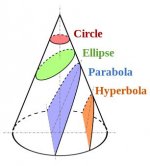
@nvr2: Very good effort. You understand the need to define source as well as load impedance just like the radio frequency folks. But surely I'd told you it was series filter, not a parallel. Different animals. They do different things. Conics in Geometry shows the relationship to my way of thinking. Parabolas versus Hyperbolas.
Anyway, here it is. A thing of great loveliness, IMO. Just like Mike Creek always used to say, every component punches its weight and does several things. The tweeter Zobel can be a 22R resistor instead. Either way is good.
@phivates: Don't go all sensitive on me. Irony is misunderstood by Americans. Why is that? Beats me...
@nvr2: Very good effort. You understand the need to define source as well as load impedance just like the radio frequency folks. But surely I'd told you it was series filter, not a parallel. Different animals. They do different things. Conics in Geometry shows the relationship to my way of thinking. Parabolas versus Hyperbolas.
Anyway, here it is. A thing of great loveliness, IMO. Just like Mike Creek always used to say, every component punches its weight and does several things. The tweeter Zobel can be a 22R resistor instead. Either way is good.
Attachments
@nvr2: But surely I'd told you it was series filter, not a parallel. Different animals. They do different things.
Anyway, here it is. A thing of great loveliness, IMO. Just like Mike Creek always used to say, every component punches its weight and does several things. The tweeter Zobel can be a 22R resistor instead. Either way is good.
System7 - Truly a thing of beauty - sorry for not full catching on to your clues earlier. I caught that you said series crossovers did something special - but then at the same time you pointed me to the ESP posting that said they were basically the same except for different sensitivities to woofer impedance changes or back EMF - so I misunderstood your message. At the time I tried my hand with a couple of Series arrangements but was completely baffled by how both HP and LP curves moved with each change of a component value. When I saw the email saying you responded to this post revealing the secret - I was both elated that I would get to see the magic and deflated for failing - so I did not open the response without going back again to your clues and trying my hand at the series crossover again. Here is where I got to with a redo of your clues - not the full answer but not bad for just 8 components
.When I get back from vacation I'll play around some more to hopefully get a deeper understanding - then maybe I'll make one of these for my Daughter. THANKS again for pushing me on this - it was fun!
Attachments
- Home
- Loudspeakers
- Multi-Way
- Why resistor in parallel with inductor in low pass crossover?