OK, in my last post I said that there are some things we can do to improve the Paraline.
First off, as Art and Nate have noted, the frequency response of the Paraline isn't as smooth as a conventional horn.

here's the measured response of Nate's Paraline, which uses a small BMS ferrite compression driver. (Can't recall the model; it's not the 4550 that's used by Danley, VTC and Yorkvile.)
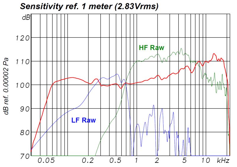
Here's the response of the VTC Paraline, using a pair of BMS 4550s. It's not perfect, but it's smoother than Nate's Paraline.
I've wasted way too much time thinking about why our Paraline's are kinda ragged, but today I had another idea of why it might be.
I think it could be due to the flat wavefront.
For instance, *all* of the Danley designed Paralines and Layered Combiners use a curvature. The curvature varies, from ten degrees in the VTC Paraline to something like ninety degrees in the Danley Layered Combiner.
At first glance, the curvature of the VTC Paraline might seem like a small thing, basically curving that wavefront so that the array can be curved.
But curving the wavefront does something else too.
Curving the wavefront changed the pathlength from the mouth of the compression driver to the exit of the Paraline. That might seem like a subtle thing, but it should have the effect of filling in the dips and smoothing out the peaks in the Paraline.
Here's why:
In a horn, we get peaks and dips in the response. These peaks and dips correspond to a long list of things, but the main ones are the distance from the driver at the throat to the exit at the mouth. The reason we build bass horns is that those resonance can augment low frequency output, but they can also create notches in the response too.. And I think that's what we're seeing in Nate's Paraline. A series of peaks and notches in the output, due to the distance from the diaphragm to the exit of the Paraline.
Now there are a few ways to fix that:
1) We could make the Paraline smaller. This would 'push' the peaks and dips higher in frequency
2) We could make the Paraline bigger. This would 'push' the peaks and dips lower. For instance, you might do this if the peaks and dips were showing up in the midrange.
But here's another options -
We can spread out the peaks and dips, by having a Paraline with a pathlength that varies by angle. Which is basically what happens when you curve a Paraline. (In a flat Paraline the distance from the exit of the compression driver to the exit of the Paraline is equal across the entire height of the Paraline. In a diverging Paraline, like the one used by VTC, the pathlength at the top and the bottom of the Paraline is longer than the pathlength at the center. This yields a curved wavefront.)
First off, as Art and Nate have noted, the frequency response of the Paraline isn't as smooth as a conventional horn.
here's the measured response of Nate's Paraline, which uses a small BMS ferrite compression driver. (Can't recall the model; it's not the 4550 that's used by Danley, VTC and Yorkvile.)
Here's the response of the VTC Paraline, using a pair of BMS 4550s. It's not perfect, but it's smoother than Nate's Paraline.
I've wasted way too much time thinking about why our Paraline's are kinda ragged, but today I had another idea of why it might be.
I think it could be due to the flat wavefront.
For instance, *all* of the Danley designed Paralines and Layered Combiners use a curvature. The curvature varies, from ten degrees in the VTC Paraline to something like ninety degrees in the Danley Layered Combiner.
At first glance, the curvature of the VTC Paraline might seem like a small thing, basically curving that wavefront so that the array can be curved.
But curving the wavefront does something else too.
Curving the wavefront changed the pathlength from the mouth of the compression driver to the exit of the Paraline. That might seem like a subtle thing, but it should have the effect of filling in the dips and smoothing out the peaks in the Paraline.
Here's why:
In a horn, we get peaks and dips in the response. These peaks and dips correspond to a long list of things, but the main ones are the distance from the driver at the throat to the exit at the mouth. The reason we build bass horns is that those resonance can augment low frequency output, but they can also create notches in the response too.. And I think that's what we're seeing in Nate's Paraline. A series of peaks and notches in the output, due to the distance from the diaphragm to the exit of the Paraline.
Now there are a few ways to fix that:
1) We could make the Paraline smaller. This would 'push' the peaks and dips higher in frequency
2) We could make the Paraline bigger. This would 'push' the peaks and dips lower. For instance, you might do this if the peaks and dips were showing up in the midrange.
But here's another options -
We can spread out the peaks and dips, by having a Paraline with a pathlength that varies by angle. Which is basically what happens when you curve a Paraline. (In a flat Paraline the distance from the exit of the compression driver to the exit of the Paraline is equal across the entire height of the Paraline. In a diverging Paraline, like the one used by VTC, the pathlength at the top and the bottom of the Paraline is longer than the pathlength at the center. This yields a curved wavefront.)
If that last post made sense, then this next post, from Danley should provide some technical detail on why this happens.
I think it's interesting, because it correlates with my listening experience with Unity horns. Which is that they have a level of 'intelligibility' which is only rivaled by single driver loudspeakers. Yet single driver loudspeakers don't do the treble as well as a good Unity horn, and single driver loudspeakers don't get as loud.
So it looks like the reasons for this come down to FOCUS

What I was getting at with Astigmatism is that in some ways (like wave propagation) sound has an analogue in light.
One big difference is that one never has a sub wavelength sized light source and only in the case of a laser does one have one frequency of coherent (as opposed to random) phase.
Also, lest a “professor” have a seizure over the misuse of a word, the following is “how I see it”.
A plane wave is what one has when one is infinitely far from a point source.
In sound, it is a wave, which has no curvature and is acoustically large enough to not disperse (a constant sound pressure vs distance).
In the optic world, this is an infinite focal length.
In the real world, a plane wave exists in a very very long pipe who’s diameter is small compared to the wavelength. Here, the pipe walls form an acoustic mirror image, having the effect of large unbounded plane wave.
A point source is one who’s focal length is less than infinity.
This can be an acoustically small sound source, in which the radiation angle is very wide, only governed by the surrounding baffle etc.
It can also be a 10 degree conical horn, in which case the radiation angle is defined by the horn wall angle, down to some loss of control frequency.
In this case, the wave that is radiated, has an equal curvature and so equal focal length in the H and V planes and spreads out at the radiation angle.
A point source or lens when distorted X vs Y, can have two focal points, this is astigmatism.
A diffraction slot CD horn is an example.
Here, the Vertical angle is set by the top and bottom angles and the focal point is the driver. In the horizontal plane, the focal point is just behind the diffraction slot.
An issue with this design is that the transition from the slot into the second half of the horn represents a large acoustic discontinuity (generally bad horn juju) which can sometimes be detected with a TEF machine as two peaks in the etc or some comb filter in amplitude.
Some related spray on optical astigmatism, in this case, the two focal points (which at the ends represent the equal path length points) are in effect the time of arrival from each plane.
CVI Laser Optics and Melles Griot Home Page
A true line source is a source, which has a focal point at infinity in the Vertical plane and at the focal point is at the aperture in the Horizontal plane.
A true homogenous source can be placed on the floor with no ill effect and the Vertical pattern is then equal to one twice as long.
A real line source array loudspeaker is usually curved (physically or electronically) as well as being made of individual sources which are mostly too far apart to add coherently.
Being curved (producing a curved wavefront, it is a point source with a large focal length in the vertical plane, down to some frequency (line length dependant) where the focal length then becomes shorter and shorter. At 20Hz (not that they would be asked to produce 20hz), a typical line array system has the focal point at the source in both planes.
An array with a small curve plus a J at the end is a third order Astigmatic system as the focal length in the Vertical plane changes from one end to the other.
So, what you really have is the individual systems directivity plus the directivity of the interaction of one box with the physical position of its mates, plus the change if the array is curved or shaded electronically.
Anytime you have more than one focal length or more than one focal point in multiple sources, you have the spreading of an impulsive signal in time or frequency dependant comb filtering due to the two or more time origins.
Josh, that is a very nice way to display it, that is that trick you came up with right?
Now, add to this the fact that one has many discrete sources too and the measurement at any one given point doesn’t tell you much.
Best,
Tom"
from : Smaart and Line Arrays
I think it's interesting, because it correlates with my listening experience with Unity horns. Which is that they have a level of 'intelligibility' which is only rivaled by single driver loudspeakers. Yet single driver loudspeakers don't do the treble as well as a good Unity horn, and single driver loudspeakers don't get as loud.
So it looks like the reasons for this come down to FOCUS
What I was getting at with Astigmatism is that in some ways (like wave propagation) sound has an analogue in light.
One big difference is that one never has a sub wavelength sized light source and only in the case of a laser does one have one frequency of coherent (as opposed to random) phase.
Also, lest a “professor” have a seizure over the misuse of a word, the following is “how I see it”.
A plane wave is what one has when one is infinitely far from a point source.
In sound, it is a wave, which has no curvature and is acoustically large enough to not disperse (a constant sound pressure vs distance).
In the optic world, this is an infinite focal length.
In the real world, a plane wave exists in a very very long pipe who’s diameter is small compared to the wavelength. Here, the pipe walls form an acoustic mirror image, having the effect of large unbounded plane wave.
A point source is one who’s focal length is less than infinity.
This can be an acoustically small sound source, in which the radiation angle is very wide, only governed by the surrounding baffle etc.
It can also be a 10 degree conical horn, in which case the radiation angle is defined by the horn wall angle, down to some loss of control frequency.
In this case, the wave that is radiated, has an equal curvature and so equal focal length in the H and V planes and spreads out at the radiation angle.
A point source or lens when distorted X vs Y, can have two focal points, this is astigmatism.
A diffraction slot CD horn is an example.
Here, the Vertical angle is set by the top and bottom angles and the focal point is the driver. In the horizontal plane, the focal point is just behind the diffraction slot.
An issue with this design is that the transition from the slot into the second half of the horn represents a large acoustic discontinuity (generally bad horn juju) which can sometimes be detected with a TEF machine as two peaks in the etc or some comb filter in amplitude.
Some related spray on optical astigmatism, in this case, the two focal points (which at the ends represent the equal path length points) are in effect the time of arrival from each plane.
CVI Laser Optics and Melles Griot Home Page
A true line source is a source, which has a focal point at infinity in the Vertical plane and at the focal point is at the aperture in the Horizontal plane.
A true homogenous source can be placed on the floor with no ill effect and the Vertical pattern is then equal to one twice as long.
A real line source array loudspeaker is usually curved (physically or electronically) as well as being made of individual sources which are mostly too far apart to add coherently.
Being curved (producing a curved wavefront, it is a point source with a large focal length in the vertical plane, down to some frequency (line length dependant) where the focal length then becomes shorter and shorter. At 20Hz (not that they would be asked to produce 20hz), a typical line array system has the focal point at the source in both planes.
An array with a small curve plus a J at the end is a third order Astigmatic system as the focal length in the Vertical plane changes from one end to the other.
So, what you really have is the individual systems directivity plus the directivity of the interaction of one box with the physical position of its mates, plus the change if the array is curved or shaded electronically.
Anytime you have more than one focal length or more than one focal point in multiple sources, you have the spreading of an impulsive signal in time or frequency dependant comb filtering due to the two or more time origins.
Josh, that is a very nice way to display it, that is that trick you came up with right?
Now, add to this the fact that one has many discrete sources too and the measurement at any one given point doesn’t tell you much.
Best,
Tom"
from : Smaart and Line Arrays
Using Danley's own measurements, I put together a chart comparing the directivity and frequency response of the Danley SH50 versus the VTC EL210.
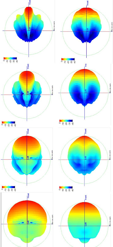
This is going to be a bit hard to read, but here goes:
1) Each row of data represents a frequency band. From the top, it's 4khz, 2khz, 1khz, and 500hz
2) Each column of data represents a loudspeaker. The one that looks about perfect is the SH-50 and the other one is the VTC EL210")
In defense of the VTC box, it's *designed* to narrow at high frequency, so that funky transition from wide coverage to narrow is a feature not a defect. When arrayed this behavior allows the boxes to reinforce each other where they need to (below 1khz) and get out of each other's way where they need to (above 1khz)
Here are the two boxes:
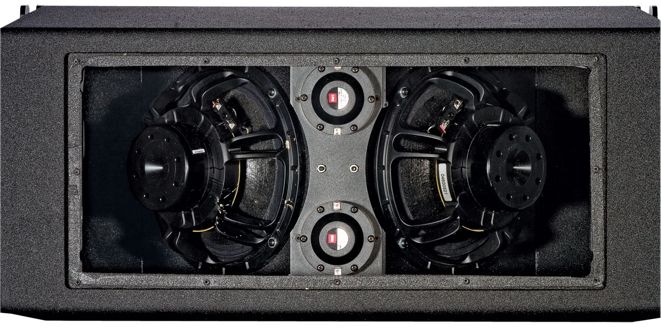
VTC EL210

Danley SH-50
This is going to be a bit hard to read, but here goes:
1) Each row of data represents a frequency band. From the top, it's 4khz, 2khz, 1khz, and 500hz
2) Each column of data represents a loudspeaker. The one that looks about perfect is the SH-50 and the other one is the VTC EL210
In defense of the VTC box, it's *designed* to narrow at high frequency, so that funky transition from wide coverage to narrow is a feature not a defect. When arrayed this behavior allows the boxes to reinforce each other where they need to (below 1khz) and get out of each other's way where they need to (above 1khz)
Here are the two boxes:
VTC EL210
Danley SH-50
 now you got me thinking about a MTM 'paraline'
Patrick,I *definitely* want to use two compression drivers per side. If I could justify the cost, I would use four. With four compression drivers, we could definitely get the xover point down to 500hz. I think with two we should be able to get it down to 700hz.
As I recall, "we" got the crossover point down to 500 Hz in many 1" exit 2 way designs built back in the middle of last century that used drivers with less output capability than are available now for far less money when adjusted for inflation.
"We" also found that small cone drivers on horns sound better than HF compression drivers at 500 Hz...
Using cones in the 6-8 inch range allows a simple two way Synergy style horn without requiring so much excursion from the HF driver as to need more than one.
Multiple HF drivers make sense for PA use, but simply are not needed for home use.
Employing multiple HF, with the attendant frequency response problems, when one driver is sufficient makes for a more difficult project with compromised results.
I'm sure you have had fun with all your abandoned Paraline-esque projects, but they simply are not the better choice compared to a simple conical horn single HF driver approach.
Good luck with your choices!
Art
I concede that those measurements of the SH50 look really good. Clearly better than the VTC EL210.
One limitation that I'm living with is a depth of about 40cm. My Summas are close to 50cm wide, and that's just waaaay too big. I can't afford to have speakers that are that imposing.
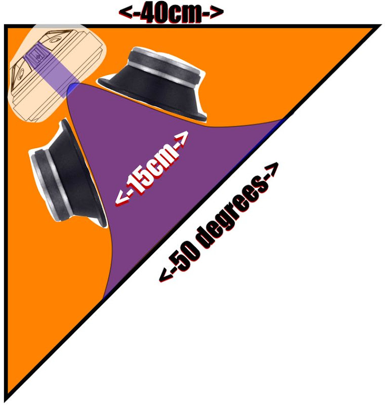
Using a depth of 40cm, here's how much Synergy horn could be squeezed into that footprint. It has the following features:
1) horizontal coverage of fifty degrees, basically because it's a good compromise between directivity and extension of the midranges
2) Width and depth of 40cm. (Basically so you can cross-fire it, like Geddes recommends with the Summas)
3) Four 5" mids (PDMR5) and a Dayton D250P at the apex
The big downside with this configuration is the mouth size; due to the size of the compression driver and the size of the cabinet, the mouth is about 15cm across before it terminates into the baffle. That equates to directivity control down to 2300hz. So basically the horn doesn't provide any pattern control for the mids, in fact it doesn't even control the compression driver beyond 2300hz.
Sure, a big horn would do a lot better, but I simply don't have space for one.
In my next post I'll see what a Paraline can do.
One limitation that I'm living with is a depth of about 40cm. My Summas are close to 50cm wide, and that's just waaaay too big. I can't afford to have speakers that are that imposing.
Using a depth of 40cm, here's how much Synergy horn could be squeezed into that footprint. It has the following features:
1) horizontal coverage of fifty degrees, basically because it's a good compromise between directivity and extension of the midranges
2) Width and depth of 40cm. (Basically so you can cross-fire it, like Geddes recommends with the Summas)
3) Four 5" mids (PDMR5) and a Dayton D250P at the apex
The big downside with this configuration is the mouth size; due to the size of the compression driver and the size of the cabinet, the mouth is about 15cm across before it terminates into the baffle. That equates to directivity control down to 2300hz. So basically the horn doesn't provide any pattern control for the mids, in fact it doesn't even control the compression driver beyond 2300hz.
Sure, a big horn would do a lot better, but I simply don't have space for one.
In my next post I'll see what a Paraline can do.
Thanks for the VTC graph PB. I was trying to find one yesterday but couldn't. I'd hope their manufactured Paralines would measure better than mine! Much tighter tolerances I'm sure. If you were to scale it similar to mine (or mine to theirs) I don't think it's really all that much worse though. The CD I was using there was the little 4524.
To me there's something distorting the waveform (giving the non-flat response other than the usual CD horn fall off), and I would say the obvious cause here is the device itself. When I built these I thought "eq can fix it." And it can........to a point.
Lately I've been reading up on Geddes' ideas, his patents and other articles. A lot of it's still pretty Greek to me, but then there's a lot that seems quite logical. Getting sound from the driver without diffraction, HOM, and with controlled directivity sounds pretty key to me. I would think that a regular Synergy/Unity horn can do this much better than any kind of Paraline variation. I would think a guy that owns a set of Summas would be working toward this goal. A Paraline just adds a lot of unnecessary complications for home use IMO.
If space is that much of a concern, maybe just stick with your little Kef egg speaker deals? I think trying to squash a Synergy design down kind of misses the point. If size is more important than directivity to you, I could see a 10" tall Paraline with the mids mounted in the device itself like I have. You'd have the eff and dynamics of a big speaker, just no pattern control.
Why not go with the smaller Lamba style horns? I'd think by now you've got at least half the drivers you'd need to make it work.
To me there's something distorting the waveform (giving the non-flat response other than the usual CD horn fall off), and I would say the obvious cause here is the device itself. When I built these I thought "eq can fix it." And it can........to a point.
Lately I've been reading up on Geddes' ideas, his patents and other articles. A lot of it's still pretty Greek to me, but then there's a lot that seems quite logical. Getting sound from the driver without diffraction, HOM, and with controlled directivity sounds
pretty key to me. I would think that a regular Synergy/Unity horn can do this much better than any kind of Paraline variation. I would think a guy that owns a set of Summas would be working toward this goal. A Paraline just adds a lot of unnecessary complications for home use IMO.If space is that much of a concern, maybe just stick with your little Kef egg speaker deals? I think trying to squash a Synergy design down kind of misses the point. If size is more important than directivity to you, I could see a 10" tall Paraline with the mids mounted in the device itself like I have. You'd have the eff and dynamics of a big speaker, just no pattern control.
Why not go with the smaller Lamba style horns? I'd think by now you've got at least half the drivers you'd need to make it work.
True, I'm not 100% sold on the Paraline.
I *do* think we can improve on it by bending the wavefront. If you look at the CLF data from the VTC EL210, it's horizontal measurements are about 80% as good as the SH50. (The SH50 clobbers it in the vertical plots that I posted earlier today, though that IS by design.)
The Summa sounds good, but it literally won't fit in my living room. So it's gathering dust in the garage, which is really quite a bummer.
The Kef is shockingly good, and my only real complaint is that it doesn't sound 'effortless' like the Summa does. It's 'thinness' can't be fixed with EQ, because it's mostly a function of the small enclosure and the directivity. Despite all this, I can listen to the Kef for hours at a time, and it's intelligibility rivals my Unity horn projects. The Kef is clearly a great option for anyone that doesn't need to go loud.
It's really hard for me to comment on the higher order modes in the Paraline.
I know that I'm hearing them, because I've trained myself to hear them from owning the Summa.
But my Paralines aren't terminated properly, and I know the main thing that causes HOMs is a discontinuity from one segment of a horn to another. (For instance, a Paraline goes from zero degrees at the entrance to ninety degrees in the span of a fraction of an inch.)
I think there's a good possibility that the HOMs in my Paraline are happening at the mouth. Then again, it's possible that they're happening inside of the device. My best sounding Paraline used reticulated foam (a la Geddes) inside of the line, and it sounded sweet. I don't want to single out the foam as being the sole reason it sounded sweet, as that Paraline also used a different midrange than all my other Paralines. (It's the one in my Youtube video named 'Smiley' with the dual Pyle PDMR5s and the Celestion CDX1-1425.)
Patrick,
Go with a 90deg width, that makes the guide shorter.
The directiviy lower frequency is set by the mouth size after the second expansion flare, which widens to avoid waistbanding per Keele's prescription....it also makes the horn shorter for the same final mouth size. So the horn mouth is bigger than your 15cm. You could make the available 50cm be the outer edge of the waistbanding flare.
I lined the inside of my Paralines (as well as the mid ports/frustums) with open cell foam too. Cleaned up the response a bit over 8khz and definitely sounds much smoother.
I agree that the Paraline mouth is difficult. I remade my mouth exit reflectors but my horn shells could use a lot of work in the transition. Even if the waveform is passing through the Paraline without diffraction/HOM the quick angle change/expansion at the mouth transition has to be a source of diffraction even with a nice gradual transition to a conical horn. I'd also say that the CD entrance is difficult to get right.....mine need work there as well
I agree that the Paraline mouth is difficult. I remade my mouth exit reflectors but my horn shells could use a lot of work in the transition. Even if the waveform is passing through the Paraline without diffraction/HOM the quick angle change/expansion at the mouth transition has to be a source of diffraction even with a nice gradual transition to a conical horn. I'd also say that the CD entrance is difficult to get right.....mine need work there as well
Good advice, and with a 90 degree horn corner mounted, the walls make the mouth area huge in the horizontal.Patrick,
Go with a 90deg width, that makes the guide shorter.
The directiviy lower frequency is set by the mouth size after the second expansion flare, which widens to avoid waistbanding per Keele's prescription....it also makes the horn shorter for the same final mouth size. So the horn mouth is bigger than your 15cm. You could make the available 50cm be the outer edge of the waistbanding flare.
Here's the current status on this project:
1) On the first page of the thread, I detailed a few options to build some speakers. It basically boiled down to either building an existing Unity or Synergy horn design, or striking out on my own. If I went out on my own, I was going to go with a Kef UNI-Q in a Synergy horn, or a pair of Dayton D250Ps in a Paraline box similar to the VTC Paraline boxes.
After spending a couple weeks weighing the options, I was leaning towards the second option. But research indicated that some of the reasons that I like the Paraline are a function of the horn geometry, nothing intrinsic to the Paraline itself. Basically, a narrow angle horn raises the output level of the compression driver in the midrange. And not by a little, by a LOT.
On a Paraline my little CDX1-1425s probably "see" about 5-10dB of gain at 1khz. That's one of the reasons the Paralines have worked so well for me. The CDX1 is struggling to get to 1khz, and the narrow coverage of the Paraline brings up the output right where I need it, at the xover point to the midranges.
The problem with the Paraline - which I'd never even considered - is PATTERN FLIP.
Basically the horizontal coverage on the Paraline boxes is consistent, because of the 90 degree walls. But the vertical coverage sloooowly narrows as we go higher in frequency. In the octave around 500-1000hz it flips. ('pattern flip')
Having listened to horns in cars for years, I'm very familiar with this distortion, it's nasty. More info and pics here:
http://www.diyaudio.com/forums/multi-way/217298-square-pegs-49.html#post3461171
Anyways, what I'm thinking about doing is a horn that's conical on the horizontal axis, and LeCleach on the vertical axis. Basically the vertical coverage won't be as even as the horizontal coverage, but 'pattern flip' will happen verrrrry gradually, which should sound better. Plus, the narrower directivity, compared to a 90x90 conical horn, will increase on-axis SPL at the xover point. That should make it easier to cross over to the mids, plus it just sounds better. (Lowers harmonic distortion.)
1) On the first page of the thread, I detailed a few options to build some speakers. It basically boiled down to either building an existing Unity or Synergy horn design, or striking out on my own. If I went out on my own, I was going to go with a Kef UNI-Q in a Synergy horn, or a pair of Dayton D250Ps in a Paraline box similar to the VTC Paraline boxes.
After spending a couple weeks weighing the options, I was leaning towards the second option. But research indicated that some of the reasons that I like the Paraline are a function of the horn geometry, nothing intrinsic to the Paraline itself. Basically, a narrow angle horn raises the output level of the compression driver in the midrange. And not by a little, by a LOT.
An externally hosted image should be here but it was not working when we last tested it.
On a Paraline my little CDX1-1425s probably "see" about 5-10dB of gain at 1khz. That's one of the reasons the Paralines have worked so well for me. The CDX1 is struggling to get to 1khz, and the narrow coverage of the Paraline brings up the output right where I need it, at the xover point to the midranges.
The problem with the Paraline - which I'd never even considered - is PATTERN FLIP.
An externally hosted image should be here but it was not working when we last tested it.
Basically the horizontal coverage on the Paraline boxes is consistent, because of the 90 degree walls. But the vertical coverage sloooowly narrows as we go higher in frequency. In the octave around 500-1000hz it flips. ('pattern flip')
Having listened to horns in cars for years, I'm very familiar with this distortion, it's nasty. More info and pics here:
http://www.diyaudio.com/forums/multi-way/217298-square-pegs-49.html#post3461171
Anyways, what I'm thinking about doing is a horn that's conical on the horizontal axis, and LeCleach on the vertical axis. Basically the vertical coverage won't be as even as the horizontal coverage, but 'pattern flip' will happen verrrrry gradually, which should sound better. Plus, the narrower directivity, compared to a 90x90 conical horn, will increase on-axis SPL at the xover point. That should make it easier to cross over to the mids, plus it just sounds better. (Lowers harmonic distortion.)
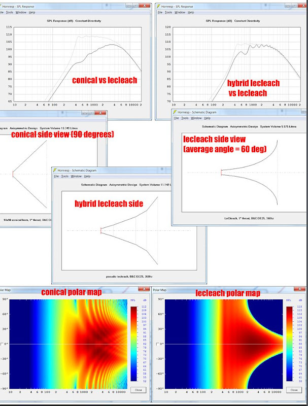
In the last post, I talked about using a LeCleach curve for the vertical axis of the horn, and a conical curve for the horizontal axis of the horn.
I put together a spreadsheet to test my hypothesis, and it's looking quite promising.
The sims above compare all three types - conical, lecleach, and my 'hybrid lecleach'
In the sims we see the following:
1) LeCleach is both the largest and the one with the greatest SPL at the xover point
2) Conical is the smallest, but it also has the lowest SPL at the xover point. Quite a big drop really; about ten decibels lower at 1khz than LeCleach.
3) Conical has the most constant coverage; LeCleach basically goes from 30 degrees of coverage at 14khz, to 90 degrees at 3khz, where the pattern rapidly widens. Conical is basically 90 degrees of coverage down to 1khz (the xover point.)
According to the SPL graphs, they 'hybrid' is somewhere in between. Not as efficient as LeCleach, but not as big either. Hornresp can't do polar plots on multi-stage horns, but I'm willing to bet that the polar plots will be somewhere in between LeCleach and conical.
Seems like a good compromise for a home Synergy horn. Basically use the larger horn size to bump up the output at the xover point, because it's hard to get the mids to play high enough. But it won't beam as much as a 'real' LeCleach horn.
Or at least that's the plan.
It's going to rain all weekend so I think I'll start building a mold tomorrow.
But first, I'm off to see Prince!
- Status
- This old topic is closed. If you want to reopen this topic, contact a moderator using the "Report Post" button.
- Home
- Loudspeakers
- Multi-Way
- What's the Easiest DIY Unity Horn Project?