I’m slowly approaching the end of this project, so I thought it would be a good idea to share here the journey.
Some background: during 2009 I designed and built my first set of speakers with a crossover. With some help on methodology I built a 2-way with a Peerless mid-woofer (830656) and a Vifa tweeter (BC25TG15-04) based only on simulations. You can see details here: http://www.diyaudio.com/forums/multi-way/140231-peerless-830656-suggestions.html
This project was successfully so I started thinking that I could do something better and had the idea to put me against 2 challenges: be able to measure what I was designing so to build a better crossover in order to use better drivers, and to build a box with curved sides.
Using the same methodology used for my first built, I performed some simulations on various mid-woofers (Peerless, Seas, Scan-Speak, SBA), and keeping an eye on various shops and sites, I finally found in April 2010 a couple of used Peerless 830883 HDS at a good price (around half of list price), and bought them. Right after, I found a special price on the Seas 27TBFC/G and bought them together with a cheap set of resistors, caps and some inductors in order to try different crossovers. Although I got the drivers by chance, both were on my short list of desired drivers for this project.
The enclosure (part 1 – the skeleton)
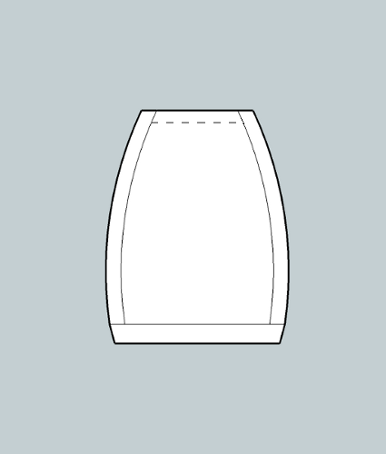
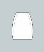
So I needed a plan in order to build a curved cabinet. I found SketchUp useful for designing the box, checking if the drivers would fit, where to put screws, port and terminals. From the top (or bottom), the enclosure would look like this:
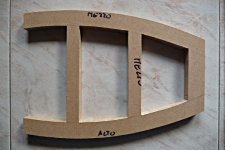
Printing a template on paper for the curved top, bottom and internal brace (all pieces are equal, only the brace has some voids in it), I was able using a jig-saw to give them the same curvature. In hindsight I would have used a router to perfectly replicate the first piece onto the other two, what I did was to tape the three pieces together and to finish the curved part with a rasp and sandpaper.
A picture of the finished brace:
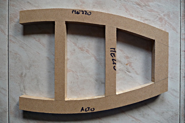
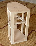
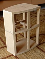
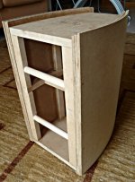
To make the enclosure skeleton and connect together the top, bottom and brace I used some 2.5 cm wide MDF pieces, and 2 full back width pieces. The result is here:
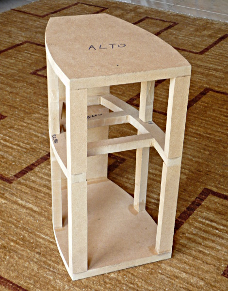
and here:
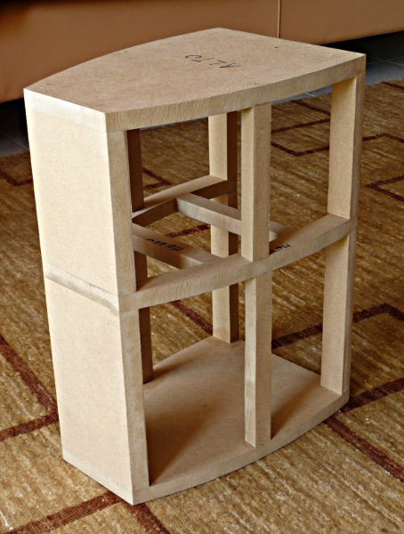
The top pieces are 14.5 cm long, and the bottom ones are 19 cm long. I found a bit difficult in properly aligning and pressing those long pieces with a small base by simply gluing them so I used also nails.
All parts here are from 16 mm width MDF.
So I needed a plan in order to build a curved cabinet. I found SketchUp useful for designing the box, checking if the drivers would fit, where to put screws, port and terminals. From the top (or bottom), the enclosure would look like this:
Printing a template on paper for the curved top, bottom and internal brace (all pieces are equal, only the brace has some voids in it), I was able using a jig-saw to give them the same curvature. In hindsight I would have used a router to perfectly replicate the first piece onto the other two, what I did was to tape the three pieces together and to finish the curved part with a rasp and sandpaper.
A picture of the finished brace:
To make the enclosure skeleton and connect together the top, bottom and brace I used some 2.5 cm wide MDF pieces, and 2 full back width pieces. The result is here:
and here:
The top pieces are 14.5 cm long, and the bottom ones are 19 cm long. I found a bit difficult in properly aligning and pressing those long pieces with a small base by simply gluing them so I used also nails.
All parts here are from 16 mm width MDF.
Attachments

The enclosure (part 2 – the curved sides)
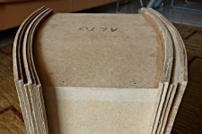
For the curved sides of the enclosure my idea was to use several thin (3 mm) MDF foils, glued one at a time. The reason is that they can be bent. To show the process of building I think that a photo speaks better than several words:
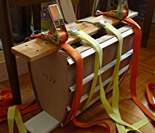
Before gluing in place, I slightly soaked the foil, and put in place for a whole day; at the end it was curved. So treated the foil returns a bit to the flat state but remains basically curved. The first foil is also a bit difficult to glue because it has very little surface to adhere to, so I used also some small nails. For the other foils (2nd to 6th) the only problem is to put an even amount of glue on the whole surface. Another recommendation is to never leave one side of the enclosure without a curved foil on it when you put pressure with the straps, because the straps can break the tiny long MDF stripes of the skeleton.
After 6+6 30x40 cm curved foils the enclosure looks so:

You can see also 2 dowels. They are removable and were used only for this building phase (and also for the veneering one), a measure against the big pressure created by the straps.
For the curved sides of the enclosure my idea was to use several thin (3 mm) MDF foils, glued one at a time. The reason is that they can be bent. To show the process of building I think that a photo speaks better than several words:
Before gluing in place, I slightly soaked the foil, and put in place for a whole day; at the end it was curved. So treated the foil returns a bit to the flat state but remains basically curved. The first foil is also a bit difficult to glue because it has very little surface to adhere to, so I used also some small nails. For the other foils (2nd to 6th) the only problem is to put an even amount of glue on the whole surface. Another recommendation is to never leave one side of the enclosure without a curved foil on it when you put pressure with the straps, because the straps can break the tiny long MDF stripes of the skeleton.
After 6+6 30x40 cm curved foils the enclosure looks so:
You can see also 2 dowels. They are removable and were used only for this building phase (and also for the veneering one), a measure against the big pressure created by the straps.
Attachments

The enclosure (part 3 - finishing)
After gluing the side panels I needed to get rid of the excess MDF. A detail of what to remove is here:
Again a photo speaks better than several words. Using a scrap MDF piece I built this “tool” to use with the router:

and placing the MDF part of the tool against the good part of the enclosure I could slowly remove all the excess.
A picture of the work in progress:

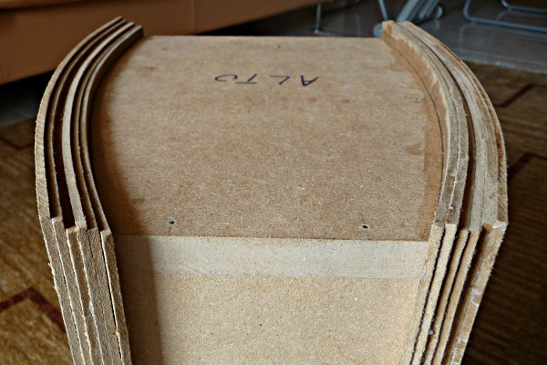
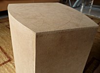
After the removal of all the excess MDF I finally added a 3 mm foil on the back (first), top and bottom, so to have a bigger thickness (16 + 3 = 19 mm). The excess on the sides of the back foil can be removed with a careful use of the above tool, and all other excess is faster removed with a flush trim bit.
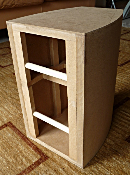
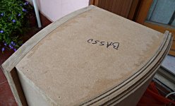
A view of the finished box:
And a detail of the back, showing the last added foils:

Now the enclosure needs to be veneered, but before I suggest to make all holes (tube and terminals on the rear) and to transfer the shape to the baffle, because a flush trim bit can leave marks on the veneer. I will cover the details in further posts (more to come).
Ralf
After gluing the side panels I needed to get rid of the excess MDF. A detail of what to remove is here:
Again a photo speaks better than several words. Using a scrap MDF piece I built this “tool” to use with the router:
and placing the MDF part of the tool against the good part of the enclosure I could slowly remove all the excess.
A picture of the work in progress:
After the removal of all the excess MDF I finally added a 3 mm foil on the back (first), top and bottom, so to have a bigger thickness (16 + 3 = 19 mm). The excess on the sides of the back foil can be removed with a careful use of the above tool, and all other excess is faster removed with a flush trim bit.
A view of the finished box:
And a detail of the back, showing the last added foils:
Now the enclosure needs to be veneered, but before I suggest to make all holes (tube and terminals on the rear) and to transfer the shape to the baffle, because a flush trim bit can leave marks on the veneer. I will cover the details in further posts (more to come).
Ralf
Attachments

The baffle (part 1)
As with my other project, I decided to have a removable baffle. It will allow easy access to the internal part of the speakers, try different damping materials and so on.
How to attach the baffle to the enclosure? If you plan to open frequently the box, as I did, you can’t use simple screws, but bolts and nuts instead. Depending on how you can access the nut location you can use a t-nut or a nut that can be simply pressed into the material. For attaching the baffle I needed the latter. I used these Serfix M4 but in the past I was able to buy a better nut similar to the barbed body insert nut – the flanged end allows the nut not to go into the wood with excessive force from the bolt.
The holes for the bolts/nuts are in the vertical MDF strips of the enclosure, horizontally centered and some 1.5 cm from top or bottom. First I built a slightly oversized test baffle on a cheap pine board, taped it to the enclosure and then drilled 2 mm pivot holes on the right locations on the baffle. Then I drilled the final holes on both the test baffle and enclosure – 5 mm diameter for a 4 mm metric bolt. The nut can be inserted into the MDF using the force from the bolt (with a washer) screwed into it.
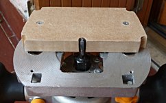
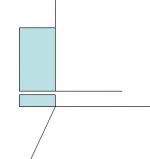
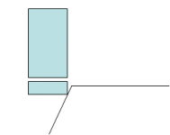
With the baffle bolted to the enclosure, the baffle can be trimmed to exact dimension with a flush trim bit. The top and bottom parts are straightforward, for the side parts some care is necessary. The reason is that the sides of the enclosure are curved so the wheel of the trim bit will transfer a profile that can be some mm wider than the enclosure, depending where the wheel is on the curve. The following picture should explain what I’m saying:
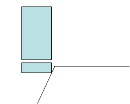
To overcome the problem, it is necessary to have some space between the enclosure and the baffle in order to put the wheel of the trim just at the edge of the enclosure as can be seen in this picture:
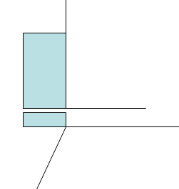
This is nearly impossible, but if you want to veneer the enclosure, and now it is not, you realize that the enclosure will become slightly wider (and taller) once veneered. So you can put the wheel of the bit some mm down the edge and transfer a slightly wider profile. With basic trigonometry, it is easy to calculate that for a 0.5 mm veneer you can move the wheel some 3 mm down from the edge, allowing a precise and easy trim of the baffle.
In my case it wasn’t possible to simply use a table saw and cut a precise panel, because the sides of the enclosure aren’t a straight line. Probably the pressure from the straps during the curved sides building phase wasn’t even (I used 2 different strap types).
Ralf
As with my other project, I decided to have a removable baffle. It will allow easy access to the internal part of the speakers, try different damping materials and so on.
How to attach the baffle to the enclosure? If you plan to open frequently the box, as I did, you can’t use simple screws, but bolts and nuts instead. Depending on how you can access the nut location you can use a t-nut or a nut that can be simply pressed into the material. For attaching the baffle I needed the latter. I used these Serfix M4 but in the past I was able to buy a better nut similar to the barbed body insert nut – the flanged end allows the nut not to go into the wood with excessive force from the bolt.
The holes for the bolts/nuts are in the vertical MDF strips of the enclosure, horizontally centered and some 1.5 cm from top or bottom. First I built a slightly oversized test baffle on a cheap pine board, taped it to the enclosure and then drilled 2 mm pivot holes on the right locations on the baffle. Then I drilled the final holes on both the test baffle and enclosure – 5 mm diameter for a 4 mm metric bolt. The nut can be inserted into the MDF using the force from the bolt (with a washer) screwed into it.
With the baffle bolted to the enclosure, the baffle can be trimmed to exact dimension with a flush trim bit. The top and bottom parts are straightforward, for the side parts some care is necessary. The reason is that the sides of the enclosure are curved so the wheel of the trim bit will transfer a profile that can be some mm wider than the enclosure, depending where the wheel is on the curve. The following picture should explain what I’m saying:
To overcome the problem, it is necessary to have some space between the enclosure and the baffle in order to put the wheel of the trim just at the edge of the enclosure as can be seen in this picture:
This is nearly impossible, but if you want to veneer the enclosure, and now it is not, you realize that the enclosure will become slightly wider (and taller) once veneered. So you can put the wheel of the bit some mm down the edge and transfer a slightly wider profile. With basic trigonometry, it is easy to calculate that for a 0.5 mm veneer you can move the wheel some 3 mm down from the edge, allowing a precise and easy trim of the baffle.
In my case it wasn’t possible to simply use a table saw and cut a precise panel, because the sides of the enclosure aren’t a straight line. Probably the pressure from the straps during the curved sides building phase wasn’t even (I used 2 different strap types).
Ralf
Attachments
The baffle (part 2)
The test baffle allowed me to play with the drivers and exercise my skill on routing. But I think it is necessary in any case in order to create a sloped border on the sides of the final baffle. I wanted the sloped border for visual appearance, refer to the first image of the thread to see what I mean.
In Italy it is difficult to find veneer and in general good wood. So I searched first the veneer, and once I found a dozen foils of birch masur veneer, I opted for a birch baffle, not a single block, because I know that single block will expand and shrink with humidity variations. The panel I found is 26 mm thick.
The test baffle is used as a template for the final baffle. The first operation is to cut the panel slightly oversized and then transfer the holes. I put the front of the test baffle onto the back of the final baffle and signed with a pencil the holes positions. I drilled first the pivot holes (2 mm) from the back to the front of the final baffle, and then the correct sized holes from the front to the back. This because I wanted to countersink the bolts so I first drilled a 10 mm wide and 6-8 mm depth hole and then a 5 mm wide hole for the remaining thickness of the baffle.
I then used a 5 mm bolt screwed from the test baffle into the final baffle. A 5 mm bolt will stay in place in a 5 mm hole without a nut, securing the two panels together. I used also a small washer between the panels. So I could easily transfer the profile with a flush trim bit. I then rounded the whole profile with the biggest roundover bit my router can handle, a 0.5” radius bit. The last operation was to angle the sides with a 15 degree bit.
The result can be seen in this photo:
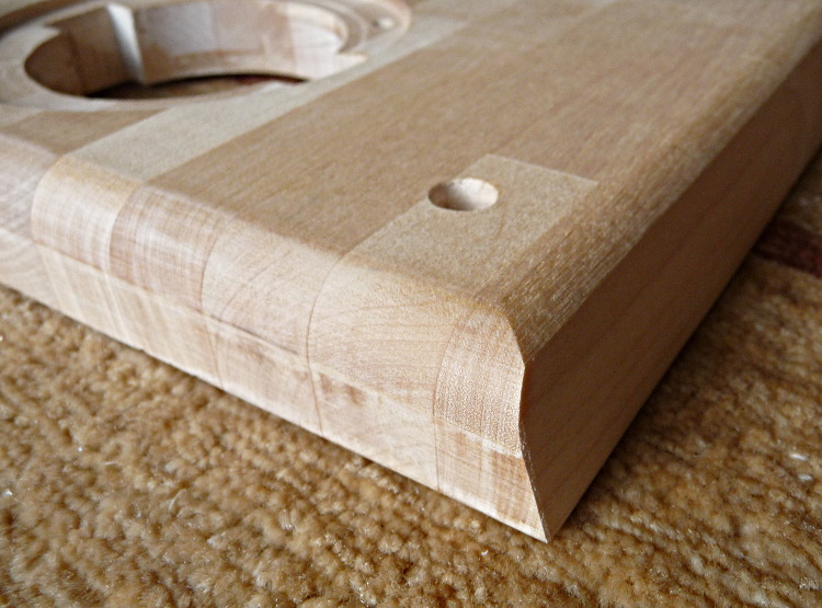
All this work with the router on a hard wood was done few mm in height at a time. The problem is that the bit should move fast on the wood because it can “burn” the wood, and this can’t be done if the bit has to remove too much material at once.
After the profile was done with the roundover and the lateral chamfer I removed the test baffle and did the drivers holes. The centers were marked right before doing the roundover, because it is easier to measure on the baffle with the edges. The tweeter is 7 cm from top, with a lateral offset of 2 cm (the 2 speakers are mirrored), the woofer is 21.5 cm from top.
A picture of the completed baffle:

On the rear I chamfered the woofer hole for better airflow:
Ralf
The test baffle allowed me to play with the drivers and exercise my skill on routing. But I think it is necessary in any case in order to create a sloped border on the sides of the final baffle. I wanted the sloped border for visual appearance, refer to the first image of the thread to see what I mean.
In Italy it is difficult to find veneer and in general good wood. So I searched first the veneer, and once I found a dozen foils of birch masur veneer, I opted for a birch baffle, not a single block, because I know that single block will expand and shrink with humidity variations. The panel I found is 26 mm thick.
The test baffle is used as a template for the final baffle. The first operation is to cut the panel slightly oversized and then transfer the holes. I put the front of the test baffle onto the back of the final baffle and signed with a pencil the holes positions. I drilled first the pivot holes (2 mm) from the back to the front of the final baffle, and then the correct sized holes from the front to the back. This because I wanted to countersink the bolts so I first drilled a 10 mm wide and 6-8 mm depth hole and then a 5 mm wide hole for the remaining thickness of the baffle.
I then used a 5 mm bolt screwed from the test baffle into the final baffle. A 5 mm bolt will stay in place in a 5 mm hole without a nut, securing the two panels together. I used also a small washer between the panels. So I could easily transfer the profile with a flush trim bit. I then rounded the whole profile with the biggest roundover bit my router can handle, a 0.5” radius bit. The last operation was to angle the sides with a 15 degree bit.
The result can be seen in this photo:
All this work with the router on a hard wood was done few mm in height at a time. The problem is that the bit should move fast on the wood because it can “burn” the wood, and this can’t be done if the bit has to remove too much material at once.
After the profile was done with the roundover and the lateral chamfer I removed the test baffle and did the drivers holes. The centers were marked right before doing the roundover, because it is easier to measure on the baffle with the edges. The tweeter is 7 cm from top, with a lateral offset of 2 cm (the 2 speakers are mirrored), the woofer is 21.5 cm from top.
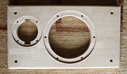
A picture of the completed baffle:
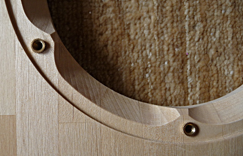
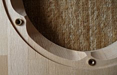
On the rear I chamfered the woofer hole for better airflow:
Ralf
Attachments

Veneer
The veneer I found is raw without any paper on back, 0.5-0.6 mm thick.
I applied the veneer one side at a time using this order: back, bottom, sides, top. First I cut the foils slightly oversized, then soaked the foils removing the excess water. In the meantime I applied PVA glue onto the enclosure and then put the foil onto the box. For the top, bottom and back I clamped the enclosure on a table, for the sides I used the same method used to build the curved sides of the enclosure, using an additional curved panel in order to even the pressure of the straps onto the veneer. In any case it is important to quickly remove any excess glue that will flood out from the pressed parts. It is also better to remove the excess veneer before it is completely dried, because else it can splinter.
There are some wrinkles and irregularities in a raw veneer so once applied I sanded it well. I also applied a primer and then sanded again. So treated the veneer is rather insensitive to dirt and can be managed well.
A full view of the veneered box, with mounted drivers:
For a while this will be probably the last woodworking post, as I will paint the enclosures not before this summer: I don’t have a suitable place for this operation and thus need to do it on the terrace. Next there will be posts about measurements and crossover.
Ralf
Attachments

Measurement devices
In the spirit of DIY I wanted to do my own measurement devices, something to measure the impedance and a microphone.
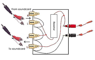
For the first device I found this simple project and built it: AudioBlog: A simple loudspeaker measurement jig for ARTA
I needed to connect it to an external USB sound card, because the integrated one of my laptop wasn’t really suited, so I bought a Behringer UCA202. I used the device with Limp and I’m really pleased with the results.
However I think it is better to post a different sketch of the device, because I had some trouble in understanding that one posted on the site:
The microphone was a different and more complex story. I started buying a Panasonic WM-61A capsule; it needs a phantom supply so I build a simple circuit with a cap, a resistor and a battery, but I realized after that I also needed a preamp. I found the Neal/Wallin project and first built the preamp on a perfboard. The main problem with this kind of board is the need to connect several points together, thus the need to use many small pieces of wire. I had many problems in the soldering phase, I eventually got it correct, but I then switched to a PCB when I learned how to make one at home. You can find info about the mic preamp here: Microphone Preamplifier Project
The problem with my microphone is that it isn’t calibrated, and I doubt I can find someone who can calibrate it. It is good to check the frequency response over a limited interval, but I was afraid to use it to measure the frequency response for example in the 100 – 10000 Hz interval. So I opted for a calibrated microphone that can use my preamp, and found this one, who came with a personal calibration file that can be used with Arta: iSEMcon GmbH
Next I will post measurements of the drivers.
Ralf
In the spirit of DIY I wanted to do my own measurement devices, something to measure the impedance and a microphone.
For the first device I found this simple project and built it: AudioBlog: A simple loudspeaker measurement jig for ARTA
I needed to connect it to an external USB sound card, because the integrated one of my laptop wasn’t really suited, so I bought a Behringer UCA202. I used the device with Limp and I’m really pleased with the results.
However I think it is better to post a different sketch of the device, because I had some trouble in understanding that one posted on the site:
The microphone was a different and more complex story. I started buying a Panasonic WM-61A capsule; it needs a phantom supply so I build a simple circuit with a cap, a resistor and a battery, but I realized after that I also needed a preamp. I found the Neal/Wallin project and first built the preamp on a perfboard. The main problem with this kind of board is the need to connect several points together, thus the need to use many small pieces of wire. I had many problems in the soldering phase, I eventually got it correct, but I then switched to a PCB when I learned how to make one at home. You can find info about the mic preamp here: Microphone Preamplifier Project
The problem with my microphone is that it isn’t calibrated, and I doubt I can find someone who can calibrate it. It is good to check the frequency response over a limited interval, but I was afraid to use it to measure the frequency response for example in the 100 – 10000 Hz interval. So I opted for a calibrated microphone that can use my preamp, and found this one, who came with a personal calibration file that can be used with Arta: iSEMcon GmbH
Next I will post measurements of the drivers.
Ralf
Attachments

Measures
I should have done this post some time ago because the measures are already done.
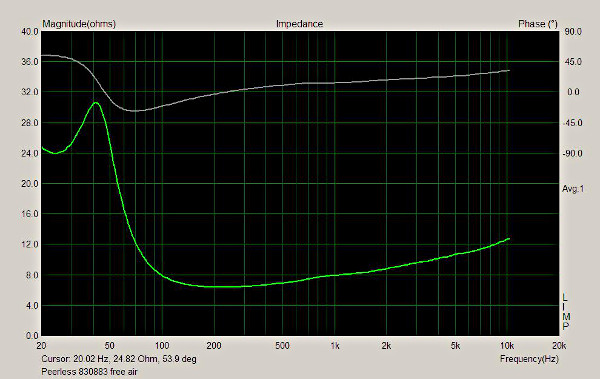
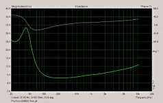
First there are the impedances of the drivers. The midwoofer:
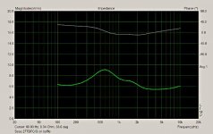
and the tweeter:
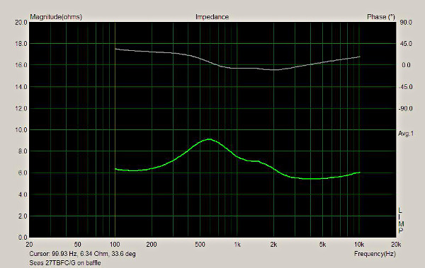
The range of valid measure is roughly 30-10K Hz with my device. For a good simulation we need impedance up to 20K Hz (40K would be better), so I added points based on the final slope. In any case, the measured impedances match the published ones.
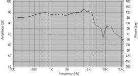
For SPL measures I opted for a gated measurement. Due to the smallness of my room, the microphone cannot be placed more than 80 from the drivers and 100-110 cm from the floor, so the gate is some 4.3 ms, and thus measures are only valid above roughly 250 Hz. My crossover point is targeted in the 1500 – 3000 Hz range, so the measures can be used.
The woofer:

Nothing unexpected here, a rise in the midrange due to the baffle, and the double breakup peaks in the 4 – 5.5 KHz range.
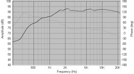
The tweeter:

Frankly, I did not expect the bump above 2 KHz, but both tweeters measure the same.
The SPL values have been modified to some more “normal” values, I don’t know if they are correct, but the two graphs are consistent each other, as I have added the same amount of SPL on both measures.
Ralf
I should have done this post some time ago because the measures are already done.
First there are the impedances of the drivers. The midwoofer:
and the tweeter:
The range of valid measure is roughly 30-10K Hz with my device. For a good simulation we need impedance up to 20K Hz (40K would be better), so I added points based on the final slope. In any case, the measured impedances match the published ones.
For SPL measures I opted for a gated measurement. Due to the smallness of my room, the microphone cannot be placed more than 80 from the drivers and 100-110 cm from the floor, so the gate is some 4.3 ms, and thus measures are only valid above roughly 250 Hz. My crossover point is targeted in the 1500 – 3000 Hz range, so the measures can be used.
The woofer:
Nothing unexpected here, a rise in the midrange due to the baffle, and the double breakup peaks in the 4 – 5.5 KHz range.
The tweeter:
Frankly, I did not expect the bump above 2 KHz, but both tweeters measure the same.
The SPL values have been modified to some more “normal” values, I don’t know if they are correct, but the two graphs are consistent each other, as I have added the same amount of SPL on both measures.
Ralf
Attachments
Finishing
It is been a long time since the last post. The speakers have been in regular use for many years, and I wanted to share the last details about the finishing and the crossover.
I wanted to obtain a shiny look on them, so I bought a glossy transparent wood paint. No idea of the composition of the paint, but the brush can be cleaned with water. I applied 10 coats with a brush, slightly sanding with 240 grit between each coat. The end result was shiny but not flat, so I had to sand it down to a flat surface. Having a relatively thick amount of paint helps in obtaining a flat surface without risking to remove all the paint in the process. I started with 400 grit to remove the most of the hilly effect, then 600 and 800. After that the surface was flat but with signs of the sanding process, so I continued with finer wet sand paper (1000, 1500 and 2000), obtaining eventually a somewhat flat even surface without sanding signs, that started to become glossy. Last work was done with a white paste specific for car paint, using a cotton tissue. The end result, while not perfect is really good.
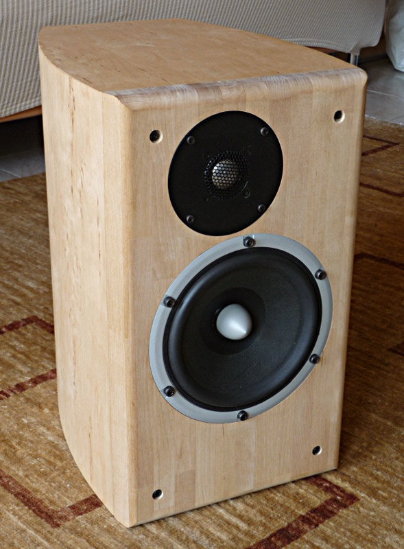
A photo of the finished speaker:
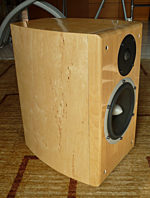
Next I will post details of the crossover and final measurements. I’m pretty confident of the crossover but want to be sure so I need to open the speakers and have a look inside (I have built some different versions, the last one when the speakers were already in use).
It is been a long time since the last post. The speakers have been in regular use for many years, and I wanted to share the last details about the finishing and the crossover.
I wanted to obtain a shiny look on them, so I bought a glossy transparent wood paint. No idea of the composition of the paint, but the brush can be cleaned with water. I applied 10 coats with a brush, slightly sanding with 240 grit between each coat. The end result was shiny but not flat, so I had to sand it down to a flat surface. Having a relatively thick amount of paint helps in obtaining a flat surface without risking to remove all the paint in the process. I started with 400 grit to remove the most of the hilly effect, then 600 and 800. After that the surface was flat but with signs of the sanding process, so I continued with finer wet sand paper (1000, 1500 and 2000), obtaining eventually a somewhat flat even surface without sanding signs, that started to become glossy. Last work was done with a white paste specific for car paint, using a cotton tissue. The end result, while not perfect is really good.
A photo of the finished speaker:
Next I will post details of the crossover and final measurements. I’m pretty confident of the crossover but want to be sure so I need to open the speakers and have a look inside (I have built some different versions, the last one when the speakers were already in use).
Attachments
Nice looking speaker, interesting to see the performance graphs/measurements.
Like the use of what looks like kitchen worktop as a front baffle. Was thinking the same, available in a number if different woods (oak, beech, birch, iroko, bamboo etc.) and usually in 27mm or 40mm deep. Off cuts often available pretty cheaply.
Like the use of what looks like kitchen worktop as a front baffle. Was thinking the same, available in a number if different woods (oak, beech, birch, iroko, bamboo etc.) and usually in 27mm or 40mm deep. Off cuts often available pretty cheaply.
Thanks Lojzek and Ugg10 for the nice words!
A lot of work has been put into building the speakers, spread over a long period of time because I don't have a dedicated facility, so everything took much more time than expected.
Yes, that kind of panel I used for the baffle can be used for kitchen tops. It has a kitchen look but it provides the stability needed for a baffle, and can be machined with good precision. A great difference with a ply panel is that it doesn't splint. Here comes in 26 and 40 mm height, I used the 26 one and think it was enough. I wasn't willing to use a MDF panel for the baffle as I couldn't veneer it and I didn't like a painted baffle against a veneered box.
I prefer to redo all the graphs, unfortunately this means I can't do them today as I have severe back pain right now and can't even walk, moving a box is out of question...
Ralf
- Status
- This old topic is closed. If you want to reopen this topic, contact a moderator using the "Report Post" button.
- Home
- Loudspeakers
- Multi-Way
- Another 6.5”+1” BR design (Peerless HDS + Seas Prestige)