I have a set of speakers that I have recapped and now would like to play with the low pass section. If I place a inductor and capacitor in standard 12db format to the low pass section, it currently has nothing, do I understand correctly I now have to reverse the polarity to this woofer. The band pass section has a 12db format and the high pass section has what I read as a 18db format with these both having the polarities swithched at the speakers. First post as a new member to this forum.
Not necessarily, and from here on in things become a little uncertain 
I would first be questioning why there is no crossover on the woofer. Is it an acceptable choice or was it a cost compromise? Chances are you could make an improvement if you knew what to do to cross the woofer better but was the mid crossed with the woofer's failings taken into consideration, meaning you'd want to tweak that one too?
With regards to polarity, if you imagine speaker phase as being somewhere on a 360 degree continuum (a circle), and the two polarities offering to add/subtract 180 degrees. If this were a compromised speaker then who's to say where on that circle it is now, and whether you wouldn't need something between those (meaning proper design with measurements). Your best bet would probably be using the pink noise test described on this site by Speaker Dave. It's not the end of the world if it isn't perfect.
If I place a inductor and capacitor in standard 12db format to the low pass section, it currently has nothing, do I understand correctly I now have to reverse the polarity to this woofer. The band pass section has a 12db format and the high pass section has what I read as a 18db format with these both having the polarities swithched at the speakers. First post as a new member to this forum.
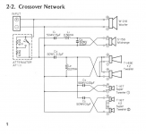
Here what I understand:
Woofer: full range (no filter)
Midrange: second order (12dB)
Tweeter: third order (18dB)
So the woofer is crossed very high, by its natural roll-off.
The midrange is most probably one of those cheap paper cones.
The tweeter is also cheap, most probably paper, but plastic is possible.
So if you add 12dB filter to the woofer (which means a lower frequency cut-off than its natural roll-off), you have to cross the midrange lower also, which means you have to replace the midrange with the one capable of lower frequency cut-off.
About phase, only certain theoretical slopes have phase difference of whole good number (such as 180deg). In practice (such as your filter), the slope is not theoretical, and the phase is not a good number.
But assuming the difference is 180deg, you can test it by ears (well, may be not easy for beginners) by switching the cable to the woofer (or midrange).
BTW, in general (as a prediction) when you add an inductor to the woofer, the phase is inverted, when you add a capacitor the phase is inverted again. So most probably you don't need to invert anything after adding the 12dB filter to the woofer.
Ok let me study that idea. I was thinking around those values on the woofer. Pulled the drivers and the woofer is marked with a frequency range of 45-1000htz and the mid at 1000-4500. do i have it right that this design was to have the woofer use only natural roll off? And do i end up with too much gap if i add the 1 mH, 7uF combo to the woofer.
Pulled the drivers and the woofer is marked with a frequency range of 45-1000htz and the mid at 1000-4500. do i have it right that this design was to have the woofer use only natural roll off? And do i end up with too much gap if i add the 1 mH, 7uF combo to the woofer.
Why do you want to change the design? Are you not satisfied with anything? The woofer break up may be? I guess the midrange is more fatiguing (due to break-up in more serious frequency) than the woofer rolling off at 1K.
A full-range woofer usually has that sonic quality that often justify some peaks/breakups. Only in more expensive design the more complex crossover can outperform the full-range strength.
A seamless crossover is a very basic requirement for a good sounding speaker. I think you will just ruin the speaker by adding the new LP filter for 2 reasons: (1) You lost the strength of full range sonic character (2) The transfer/crossover may not as seamless as before.
I have always enjoyed these speakers with their "vintage" sound. They have the Alnico characteristics to them. I have much higher end speakers but always drifted back to these. I happen to have numerous sets of these from when my dad was in wholesale hifi sales and have been developing a cabinet which will basically incorporate two sets of these into each speaker. So I was trying to figure out if I could improve on covering the low section by keeping one woofer full range and filtering one down lower in the range. Maybe the mid-range area might be a better area to gain a little more punch. If i do the cross over in a plug and play style in could change things easy enough and listen.
It's already a 3-way (4-way?!) Nothing to be improve, but wait...So I was trying to figure out if I could improve on covering the low section by keeping one woofer full range and filtering one down lower in the range. Maybe the mid-range area might be a better area to gain a little more punch.
It can not hurt you testing a very small coil in the woofer, making the mid section more alive. I doubt this will work with proper tools for measuring parameters and simulation. Another test/experience would be using a more alive mid like connecting the 2nd woofer in the place of the mid just for your pleasure of mind (the treble will not be that good but maybe the output).
Now, I would do as an example, for like the Dynaco 25 (2-way), I would use the woofer for mids and just add a woofer making it a 3-way. Now the nice sounding paper driver is free to make it's free full range duty at the place of a real mid driver. This can be done if you know what you are doing, but sure it's a great sound. A new version of the Dynacos, not something that was easy to do for Peter Comeau when it found himself full of problems and the new complexity of brand new crossovers for the brand new drivers away from the simplicity of the originals cap/1 component crossover, a vintage design and piece of engineering that was loved around the world until today with a surprising pleasant and natural sound for all types of music.
http://user.faktiskt.se/M_N/WD25T_Part1.pdf
In looking at xo points in post #6 and the schematic I think the woofer would see frequency out of its range by connecting to mid range. This is a very bright sounding speaker with the attenuator capable of placing 6.8 ohms, 15 or nothing to the mid and high sections to cut them back. I rarely use its resistive function.
- Status
- This old topic is closed. If you want to reopen this topic, contact a moderator using the "Report Post" button.
- Home
- Loudspeakers
- Multi-Way
- Crossover help