Hey guys, I'm new to speaker building and am doing Paul Carmody's Hitmakers as my first project, and just wanted to post a picture of the crossover before i glue it to make sure that everything is set up properly.
Crossover Schematics:

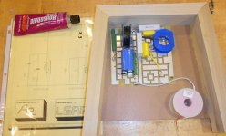
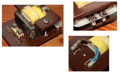
My crossover: (Sorry for bad quality)

Thanks in advance!
Crossover Schematics:
My crossover: (Sorry for bad quality)
Thanks in advance!
Nobody can judge whether it is correct or not because (1) your photo doesn't show where the speakers and amp connect to the network, (2) your photo doesn't show what values of capacitance, inductance and resistance are connected where, , and (3) the connections and the components(s) at the top of the photo are not visible.
There are some photo-editing programs that would allow you to add component values to the photo, but of course you don't necessarily have such a program.
Really, it would be fairly simple for you to decide for yourself by carefully comparing what you have soldered together to the schematic of the cross-over network.
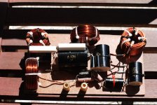
One inductor on its side and the other one upright is correct to reduce interaction between the two fields.
Regards,
Pete
There are some photo-editing programs that would allow you to add component values to the photo, but of course you don't necessarily have such a program.
Really, it would be fairly simple for you to decide for yourself by carefully comparing what you have soldered together to the schematic of the cross-over network.
One inductor on its side and the other one upright is correct to reduce interaction between the two fields.
Regards,
Pete
Last edited:
Suggest that you sketch it up on computer ("Paint" Program on a PC). Add all the values; also add/post the schematic if you have one.
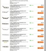
Here are some inexpensive boards to dress up your project: The Madisound Speaker Store
Here are some inexpensive boards to dress up your project: The Madisound Speaker Store
No doubts- math it's not an opinion....
The input is at the left, power to the woofer is taken from the joints from the coil, the little cap paralleled to it and the cap that goes to ground; the ground point is at the right where the parallel to ground coil of the 2nd order filter refers to, as also the parallel to ground resistor of the tweeter which is part of the L-pad, indeed the signal going to the tweeter is taken at the joint of the two resistors, up right.
Also, if physic's not an opinion, my suggestion for keeping the circuit out of the box...
Thanks for the responses, and sorry the picture was so unclear, but picowallspeaker was correct in his interpretation of it.
Here's what I have doodled in paint.
I posted a picture of the schematic in the first post, but I guess people are having trouble seeing it. If you can't see the schematic in the original post, here is the build write-up for the speakers. The crossover schematic is about halfway down the page.
https://sites.google.com/site/undefinition/hitmakers
Here's what I have doodled in paint.
An externally hosted image should be here but it was not working when we last tested it.
I posted a picture of the schematic in the first post, but I guess people are having trouble seeing it. If you can't see the schematic in the original post, here is the build write-up for the speakers. The crossover schematic is about halfway down the page.
https://sites.google.com/site/undefinition/hitmakers
It looks like your soldering correctly corresponds to the schematic. If it were me, I'd try to make the connections rectangular and keep the wire leads of the components straight, but doing that is not really necessary for it to function correctly.
If you were to use at least a few terminal strips, especially for the connections to the speakers and amp input terminals, in assembling the network, that would help to insure that the connections stay solid. Making a good solder joint with three or more wires twisted together is somewhat difficult and doesn't look great.
Terminal strips, several metallic terminal eyes riveted to a length of phenolic are no longer widely available but are still sold by Mouser Electronics. Radio Shack still sells them, I believe, but what they have are very flimsy. This is most applicable if you are in the US.
Regards,
Pete
I looked into the terminal strips; they're expensive. The Matrix board seems like the best around for $7.50. The quality is very nice.
If on a budget, one thought is to bend up wire crimp ends, use small screws to hold them in place for a solder joint.
Tip of the day: Goop in the red tube is really nice glue for holding parts, can find it just about anywhere, grocery/drug stores.
If on a budget, one thought is to bend up wire crimp ends, use small screws to hold them in place for a solder joint.
Tip of the day: Goop in the red tube is really nice glue for holding parts, can find it just about anywhere, grocery/drug stores.
Construction cement (in a long cardboard tube) is also very good for cementing components to a circuit board or wooden base. Try Loctite PL375. Of course there is way too much of the glue for just the circuit board, but it can be also used for the joints of a wooden speaker box.
Another economical alternative for wire joints is a 6D wire nail. This will work if your base is fairly thick wood, I think 3/4" would be thick enough. Drive the nail into the base where you want to tie several connecting wires, wrap the component leads/ wires around the nail, and solder. Actually I never have done this with a cross-over network, but did do it at least a few times with some other circuits a good long time ago.
Strangely, in maybe the past ten years, I've found it difficult to find wire nails. However, it is very easy to find very substantial, thick, 6D nails. For many types of construction with wood, a wire nail holds things together well enough. In fact, the thicker nails that are now more prevalently sold tend to split wood. I wonder why that is? I think the answer is that nails are mostly sold by weight.
Regards,
Pete
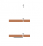
Couple of ideas for terminals -
MCM has 25 packs of these solder tabs (screen shot)
These could also come in handy:
http://www.amazon.com/Solder-Tabs-B...F8&qid=1363941880&sr=8-1&keywords=solder+tabs
MCM has 25 packs of these solder tabs (screen shot)
These could also come in handy:
http://www.amazon.com/Solder-Tabs-B...F8&qid=1363941880&sr=8-1&keywords=solder+tabs
Attachments
I used Masonite and enameled copper wire for making my crossover. Drill holes in the Masonite where ever you need a component, and hold it down with a cable tie ")
Mine are externally mounted... more pics here --> http://www.diyaudio.com/forums/multi-way/68301-my-morel-mtm-project-7.html#post2740570
Tony.
Mine are externally mounted... more pics here --> http://www.diyaudio.com/forums/multi-way/68301-my-morel-mtm-project-7.html#post2740570
Tony.
Attachments
Odougbo,
Be certain that you have a window open when using that Goop- the fumes could kill you! I know, I've used it, and it certainly does produce a strong bond; however it also contains a lot of nasty chemicals.
Sy, a member here, I think is a chemist. He should tell us all about Goop.
-Pete
Be certain that you have a window open when using that Goop- the fumes could kill you! I know, I've used it, and it certainly does produce a strong bond; however it also contains a lot of nasty chemicals.
Sy, a member here, I think is a chemist. He should tell us all about Goop.
-Pete
The spay adhesives scare me that stuff will make your head spin.
I used to use household silicon, but they must have change the formulas, it doesn't seem to work as good as it used to.
There's always hot glue sticks, which works very well sealing wires going through speakers walls.
that stuff will make your head spin. I used to use household silicon, but they must have change the formulas, it doesn't seem to work as good as it used to.
There's always hot glue sticks, which works very well sealing wires going through speakers walls.
Hot glue seems to be great for securing caps, inductors, resistors and wires to an xover board. It is easier than drilling holes and using cables ties. Can the glue used in hot glue guns damage any of the components?
Thanks,
henrylrjr
In my experience, hot glue doesn't make that strong of a bond. Construction adhesive is the best for securing components to a crossover board.
-Pete
- Status
- This old topic is closed. If you want to reopen this topic, contact a moderator using the "Report Post" button.
- Home
- Loudspeakers
- Multi-Way
- First crossover assembly