Cute setup, DimZ. What do you think of that Eminence Deltalite? I like the white horn--is it DIY?
thanks
i like the deltalite, fast and accurate, could use some more low end tho ...
the horn isnt diy, its from an ebay seller under the name of mast_mutter real name Werner Jagusch(eBay Canada Seller: mast mutter: on eBay.ca at low prices) ...and they are trully great ...


Sorry folks, I don't know why those pictures come out so big. Here is my secomd effort, as far as speakers are concerned. Each build I (we, friend and I) build 2 pair. These are almost exactly Zaph bamtm's. I changed the volume slightly, used better (my opinion) components, and cnc'ed internal braces and front baffles. Again, these sound amazing. I did NOT expect such excellent and clear bass.


![Photo_081209_023[1].jpg](https://www.diyaudio.com/community/data/attachments/181/181027-e830d46854cbd0252ebf3162061aaf62.jpg "Photo_081209_023[1].jpg")
I thought I had better shots. I guess I'll have to take more. These have not been veneered as of yet.
I thought I had better shots. I guess I'll have to take more. These have not been veneered as of yet.
Hello everyone!
I`m new to this forum and after seeing all pictures some of you sharing with the others I decided to show my own constructions. The speakers and crossovers I`ve bought as a kit called RX1. Speaker boxes are made to look like Sonus Faber - Concerto Domus.
I`m new to this forum and after seeing all pictures some of you sharing with the others I decided to show my own constructions. The speakers and crossovers I`ve bought as a kit called RX1. Speaker boxes are made to look like Sonus Faber - Concerto Domus.
An externally hosted image should be here but it was not working when we last tested it.
An externally hosted image should be here but it was not working when we last tested it.
An externally hosted image should be here but it was not working when we last tested it.
An externally hosted image should be here but it was not working when we last tested it.
An externally hosted image should be here but it was not working when we last tested it.
Banned
Joined 2002
Hopefully, this time pictures are bigger.
^^^ very sexy looking speakers, VERY nice work!
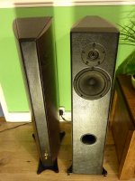
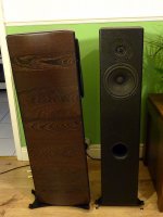
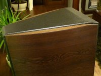
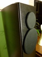
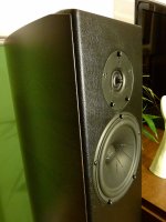
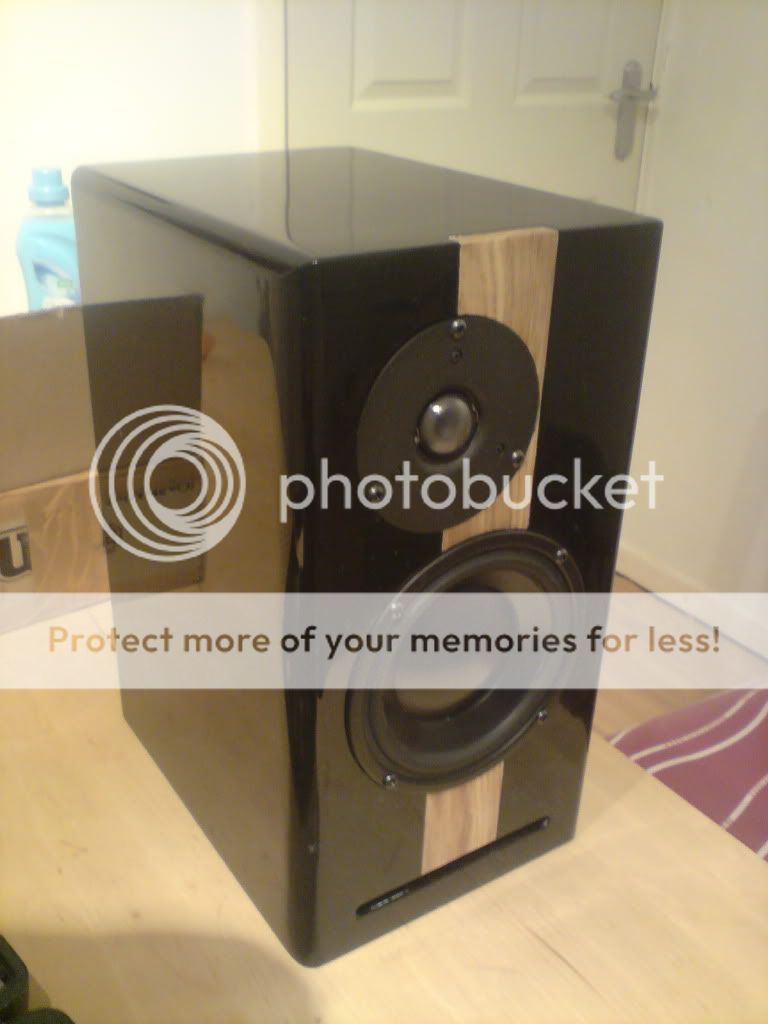
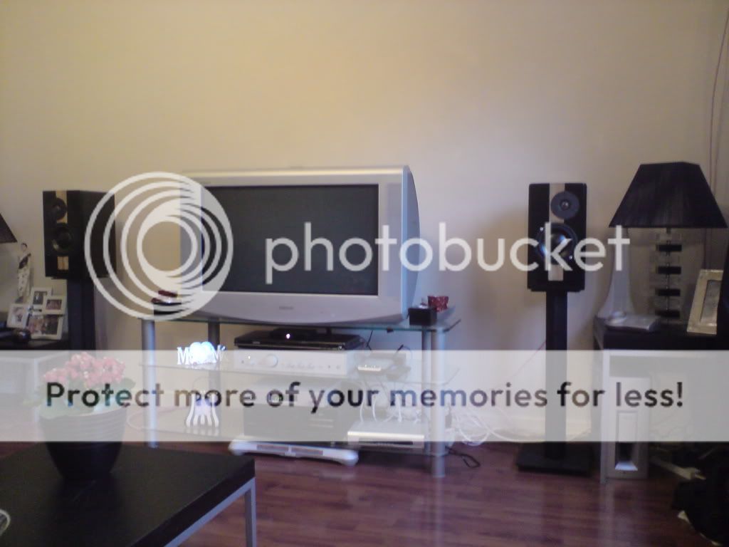
Hi everyone, This is a set of speakers I built about a year ago, with help from this forum, Its a bass reflex with morel drivers..
Not happy with the midrange from these speakers (any ideas??). but happy with how they turned out for my first diy build..
1.
2.
3.

4.
Not happy with the midrange from these speakers (any ideas??). but happy with how they turned out for my first diy build..
1.
2.
3.
4.
Last edited:
wow if that's a 63" plasma that's a massive room :O
You said it. 63" plus 2 A7s with room to spare. That room must be 20 feet wide.
room is right at 3,000 CU ft.
Wow! 1 SVS 13 is adequate? I know it gets support from the A7 even then...just one?
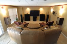
room is 17' X 22' and 8' height,, built specifically for the HT,,
have special acoustic ceiling by Armstrong with a NRC (noise reduction class) of .90,, absolutely no echo or bounce in the room,, room is very silent until everything is powered up,,
the one SVS 13 is very adequate,, have a friend running two and they do offer a "little" more punch but not worth the $$,, guess it depends on how much ya want to rattle the windows and have the wife yell at ya from upstairs,, certainly plenty of SPL for my ears,, when you can feel the LFE in the furniture your setting in, I figured that was the impact I was seeking,,
Derry
....
guess it depends on how much ya want to rattle the windows and have the wife yell at ya from upstairs,, ...
LoL
It'd be a very practical 'SPL meter', though
 And I totally agree.
Nice setup
I moved into a new apartment at the beginning of the summer and the following is the current incarnation of my system;

From 70hz to 300hz my fabulous midbass horns get the job done. These are an exponential horn with an eminence beta ten driver.
do you have any construction specs on these midbass horns?
Collection of DIY Speaker Designs
Students at Michigan Tech are publishing speaker designs at:
Tech Speakers
A few highlights:
Super flat two-way tower for studio monitor usage:
Monitor 1 by Keith Kinnear Tech Speakers
A single driver horn system:
?Audrey? Horn-loaded Single-driver Loudspeaker System ? by Nathan P.*Miller Tech Speakers
A system with an exceptionally low tweeter crossover:
BB 2-Way Loudspeakers Tech Speakers
All are released under creative commons licenses and all include testing on specific drivers. Hope some of you find this interesting and maybe useful. Let me know if there are things that would make it more useful.
Wow. Lucky students. Keith's Monitors are truly impressive, and Brad's captions for his Odyssey speakers are a riot.
Here are some things I noticed:
Some of the photos will enlarge and some won't.
I also noticed all the impedance plots have a magnitude (dB) scale which doesn't make a whole lot of sense.
Are the distortion plots showing THD2 and THD3? Also are all the students measuring distortion at the same volume or with the same power input?
DJ's towers look to me like MLTLs. Especially from the impedance plot.
Good stuff.
Roger:
Thanks for the feedback. I'm working on getting the students to do everything as similar as possible so that valid comparisons can be made and I get a little better every time I do this. I have noticed the photo issues and this semester our impedance jig quit working and then started producing strange results (like DJ's) so I have to rebuild it and figure out why it is so unhappy, especially since there is so little to go wrong... and yet.
I also have to see if our measurement system will output impedance on a more relevant scale. For our internal purposes it hasn't been all that important as you can get the data we need in some other screens. Now that they are going up on the web I need to provide some instructions on generating a more relevant plot.
We just started using the distortion plots and I need to talk with the author of the measurement software to get a better sense of exactly what they are showing. Currently nothing is labeled. This year we sort of dived in with the distortion measurements with out planning out their addition from the start so they are not calibrated tests. There are a number of other ways that the tests are not calibrated as well and since we are putting these test up online I'm going to be spending some significant time nailing down some of those issues so the data is as comparable as possible. I plan on adding another page that will detail the specifics of how all measurements are done so that it is easier for viewers to evaluate the validity of the tests.
Here you go, my latest project, 3 way floorsatnding:
(page is translated with google translate - so there could be some misunderstandings)
click below
Google Translate
(page is translated with google translate - so there could be some misunderstandings)
click below
Google Translate
- Home
- Loudspeakers
- Multi-Way
- System Pictures & Description