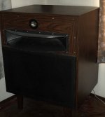
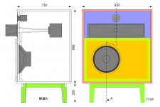
Speaker Unit :
Woofer : JBL 2215A (- 560Hz),
Squawker : JBL LE85 + Coral AH500 (370Hz - 5.4kHz),
Tweeter : Fostex T925 (5.4kHz -)
Cabinet :
Internal volume: 500 liters
Structure: Closed type
Drive :
Channel divider : handmade 3 Way 24dB/oct (with low boost)
Power Amplifier: 3 sets of LUX A501
Supplement :
I replaced the surround edge with
a non-woven (semi-permanent life) surround edge
instead of urethane surround edge.
Attachments
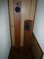
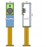
Speaker Unit :
Woofer : Wavecor WF118WA01(~2kHz)、
Tweeter : Dayton ND20FB-4(2kHz~)
Cabinet :
Internalvolume: 17 liters
Structure: Closed type
Supplement :
When placed in a corner of a room,
there is almost no need for low boost
because the low range rises due to
the baffle effect (corner horn effect).
Woofer : Wavecor WF118WA01(~2kHz)、
Tweeter : Dayton ND20FB-4(2kHz~)
Cabinet :
Internalvolume: 17 liters
Structure: Closed type
Supplement :
When placed in a corner of a room,
there is almost no need for low boost
because the low range rises due to
the baffle effect (corner horn effect).
Attachments
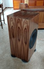
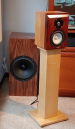
I just completed a new active 3 way system. I used a pair of Hypex Fusion FA253 amps.
Woofers are SBA SB34NRX75-6 (12 inch drivers), in 70 liter sealed boxes. The ideal sealed box for this woofer is about 110 liters, so I used a Linkwitz transform to adjust the response. boost starts at 38 Hz, and by 26 Hz I have 6 db of boost.
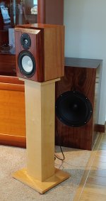
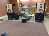
I built separate woofer cabinets to give me placement flexibility. The Hypex amps are located in the speaker stands.
The mids are SBA SB17CAC35-4, an aluminum/ceramic 6 inch driver. The box is 10 liters sealed. The cabinets have 1.5 inch roundover on the sides, and a 30 / 60 degree dual bevel along the top.
The tweeters are SBA SB26CDC-C000-4, an aluminum/ceramic dome.
Crossovers are 4th order LR at 200 Hz and 2 kHz.
I have a more detailed thread here:
New active 3-Way, Hypex and SB
Woofers are SBA SB34NRX75-6 (12 inch drivers), in 70 liter sealed boxes. The ideal sealed box for this woofer is about 110 liters, so I used a Linkwitz transform to adjust the response. boost starts at 38 Hz, and by 26 Hz I have 6 db of boost.
I built separate woofer cabinets to give me placement flexibility. The Hypex amps are located in the speaker stands.
The mids are SBA SB17CAC35-4, an aluminum/ceramic 6 inch driver. The box is 10 liters sealed. The cabinets have 1.5 inch roundover on the sides, and a 30 / 60 degree dual bevel along the top.
The tweeters are SBA SB26CDC-C000-4, an aluminum/ceramic dome.
Crossovers are 4th order LR at 200 Hz and 2 kHz.
I have a more detailed thread here:
New active 3-Way, Hypex and SB
Attachments
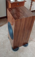
Great looking wood.I just completed a new active 3 way system. I used a pair of Hypex Fusion FA253 amps.
Woofers are SBA SB34NRX75-6 (12 inch drivers), in 70 liter sealed boxes. The ideal sealed box for this woofer is about 110 liters, so I used a Linkwitz transform to adjust the response. boost starts at 38 Hz, and by 26 Hz I have 6 db of boost.
I built separate woofer cabinets to give me placement flexibility. The Hypex amps are located in the speaker stands.
The mids are SBA SB17CAC35-4, an aluminum/ceramic 6 inch driver. The box is 10 liters sealed. The cabinets have 1.5 inch roundover on the sides, and a 30 / 60 degree dual bevel along the top.
The tweeters are SBA SB26CDC-C000-4, an aluminum/ceramic dome.
Crossovers are 4th order LR at 200 Hz and 2 kHz.
I have a more detailed thread here:
New active 3-Way, Hypex and SB
How did you like working with the Hypex Filter Designer? I found it pretty intuitive after the first few hours.
I agree. It is easy to use. I had a little learning curve to using my USB microphone (Omnimic) with the HFD software. But after a while it became second nature.
I put the amps in the stand because I wanted the system to be modular and I wanted easy quick access to the amps. I intend to make additional satellites in the future, so those are easy to swap out. If the amps were located in the satellites it would complicate this goal. If the amps were located in the woofer cabinets, the access would be poor because the cabinets are pressed up against the wall most of the time... plus the amps have large vent holes, so they need their own sub-compartment to avoid sonic leakage. Putting them in the stand solved many issues. It just resulted in the stands having a large cross section... they are beefy.
Last edited:
Four way active speaker, transconductance amps, miniDSP crossover
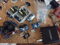
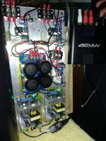
I built a four way active speaker last year. I wanted transconductance (high output impedance) amplifiers and didn't want it to be too heavy, so I put together my own plate amp with switching power supplies. It has three XY LM3886 chip amp boards, less than $10 ea on ebay, and two 24V 4A isolated switching power supplies WX-DC2412S, also on eBay or even Amazon now. To get these amps to run as transconductance amplifiers, a 0.5 ohm resistor is used to connect negative lead to the speaker to the amplifier. A wire is then run from from the negative terminal of the speaker to the inverting input of the amplifier. You now have a current output amplifier. Very simple. The miniDSP 2x4 hd for each speaker crossover allows all the filtering you could want. A 250W plate amp from Dayton Audio drives the woofer. Seas 19mm dome, Aura 2" midranges, Seas 8" W22EX001, Scan Speak Discovery 12" woofer, sealed enclosure.
I built a four way active speaker last year. I wanted transconductance (high output impedance) amplifiers and didn't want it to be too heavy, so I put together my own plate amp with switching power supplies. It has three XY LM3886 chip amp boards, less than $10 ea on ebay, and two 24V 4A isolated switching power supplies WX-DC2412S, also on eBay or even Amazon now. To get these amps to run as transconductance amplifiers, a 0.5 ohm resistor is used to connect negative lead to the speaker to the amplifier. A wire is then run from from the negative terminal of the speaker to the inverting input of the amplifier. You now have a current output amplifier. Very simple. The miniDSP 2x4 hd for each speaker crossover allows all the filtering you could want. A 250W plate amp from Dayton Audio drives the woofer. Seas 19mm dome, Aura 2" midranges, Seas 8" W22EX001, Scan Speak Discovery 12" woofer, sealed enclosure.
Attachments
Love the idea of your speakers. Can’t guess how they would sound.
Well before equalization, the six midrange drivers tended to dominate a bit. After I did my best with the miniDSP with linkwitz transforms and crossovers, I used the free Align2 software to produce a FIR filter to really flatten the response. The drivers were selected for flat response, low distortion and large X-max. The woofer has a full 25 mm peak to peak linear travel. So the system can produce 115 dB SPL over the whole range (that's why I needed six midranges). The boxes are minimum size for each driver, stuffed tight with damping material and the transient response is amazing. With all those drivers and SPL capability, drums have a real life punch that isn't available on most speakers. At normal listening levels, there is only about 0.1% distortion measured with my microphone. The cabinet shape was inspired by the Grimm Audio speakers.
Last edited:
Seas 19mm dome, Aura 2" midranges, Seas 8" W22EX001, Scan Speak Discovery 12" woofer
Er...I got one "Whisper" 2" and a Seas RLY12 and it's enough!
")
Wonder what would happen with an 8"
To get these amps to run as transconductance amplifiers, a 0.5 ohm resistor is used to connect negative lead to the speaker to the amplifier. A wire is then run from from the negative terminal of the speaker to the inverting input of the amplifier. You now have a current output amplifier. Very simple.
Very nice setup!
Do you know, using the method you described works for other chip amps?
LM1875 I have in mind.
Other chip amps configured for transconductance?
I tested the idea first using LTSpice and Tina from Ti. As TI makes the LM3886, I assumed their spice model was going to be accurate. I made an electrical LRC... model of the driver and then when it was working with the stock voltage amp schematic, made the change, adding the series resistor and feedback connection. The stability was fine. I can't see why it wouldn't work with other chip amps like the LM1875. The miniDSP is key in controlling the low end response with the current drive. I used a Linkwitz transform to transform the underdamped low end response of each driver, moving the roll off frequency and changing the damping to 0.707 to form half of the 4th order LR crossover filter. A second 0.707 damping high pass filter completes the crossover. The Linkwitz website has a spreadsheet for calculating the filter coefficients. You just have to use the 96 kHz sample rate of the miniDSP filters. The book Current-Driving of Loudspeakers by Merilainan goes into detail on the benefits of current drive.
Very nice setup!
Do you know, using the method you described works for other chip amps?
LM1875 I have in mind.
I tested the idea first using LTSpice and Tina from Ti. As TI makes the LM3886, I assumed their spice model was going to be accurate. I made an electrical LRC... model of the driver and then when it was working with the stock voltage amp schematic, made the change, adding the series resistor and feedback connection. The stability was fine. I can't see why it wouldn't work with other chip amps like the LM1875. The miniDSP is key in controlling the low end response with the current drive. I used a Linkwitz transform to transform the underdamped low end response of each driver, moving the roll off frequency and changing the damping to 0.707 to form half of the 4th order LR crossover filter. A second 0.707 damping high pass filter completes the crossover. The Linkwitz website has a spreadsheet for calculating the filter coefficients. You just have to use the 96 kHz sample rate of the miniDSP filters. The book Current-Driving of Loudspeakers by Merilainan goes into detail on the benefits of current drive.
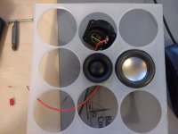
Midranges around tweeter
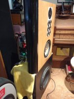
The tweeter I used has a very large diameter magnet that didn't lend itself to that. I did start a baffle (see pic) with a smaller tweeter, but I wasn't sure that tweeter was the quality I wanted.
The next build will also include making the box for the 8" driver a half cube, like the woofer box, to raise the frequency of the first internal mode.
The woofer boxes are separate, so moving them to the corners is an good thing to try. I may also try them flat on the floor facing up as Grimm Audio does it.
Cool.Nice build. I would put the mids around the tweeter. I would also put the speakers on stands and place the subs in the corners.
The tweeter I used has a very large diameter magnet that didn't lend itself to that. I did start a baffle (see pic) with a smaller tweeter, but I wasn't sure that tweeter was the quality I wanted.
The next build will also include making the box for the 8" driver a half cube, like the woofer box, to raise the frequency of the first internal mode.
The woofer boxes are separate, so moving them to the corners is an good thing to try. I may also try them flat on the floor facing up as Grimm Audio does it.
Attachments
Cool.
The tweeter I used has a very large diameter magnet that didn't lend itself to that. I did start a baffle (see pic) with a smaller tweeter, but I wasn't sure that tweeter was the quality I wanted.
The next build will also include making the box for the 8" driver a half cube, like the woofer box, to raise the frequency of the first internal mode.
The woofer boxes are separate, so moving them to the corners is an good thing to try. I may also try them flat on the floor facing up as Grimm Audio does it.
Oh and, please let those mids "breathe", or even better run them open back (open baffle)
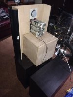
Midrange enclosures, heavy steel pipe, stuffed with fiberglass
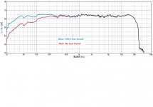
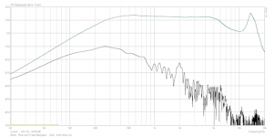
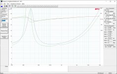
While that seems like a good idea, it didn't work out so well for me. I didn't bother saving the test result from that configuration, but I recall it was bad, as it lead me to try many other ideas. This driver has a short tube behind the dome formed by the magnet. That tube, like any tube, has resonances. So without anything attached I recall it messed up the upper frequency range. This is also a very light weight driver and as such will put energy into the front baffle, so I added mass to it with the heavy metal pipe. The goal was to have the driver mass 1000 x the mass of the dome. This gives 60 dB attenuation of the driver body relative to the dome and keeps the front baffle still. The pipe is now stuffed tightly with fiberglass to damp all the sound. The response from this treatment is totally flat and resonance free. I tested probably 10 different enclosures for this driver and this was almost best. A longer pipe is a tiny bit better, but it gets too heavy. See the response plot for one 2" driver below. The black line is from the front at the dome, The lower grey line was at the back of the tube, 30 dB down or more for the range I use the driver. If I seal the back the reflected sound would be 60 dB down when it bounced back to the front again. That was the best I could get from all the configurations I tested.
Oh and, please let those mids "breathe", or even better run them open back (open baffle)
While that seems like a good idea, it didn't work out so well for me. I didn't bother saving the test result from that configuration, but I recall it was bad, as it lead me to try many other ideas. This driver has a short tube behind the dome formed by the magnet. That tube, like any tube, has resonances. So without anything attached I recall it messed up the upper frequency range. This is also a very light weight driver and as such will put energy into the front baffle, so I added mass to it with the heavy metal pipe. The goal was to have the driver mass 1000 x the mass of the dome. This gives 60 dB attenuation of the driver body relative to the dome and keeps the front baffle still. The pipe is now stuffed tightly with fiberglass to damp all the sound. The response from this treatment is totally flat and resonance free. I tested probably 10 different enclosures for this driver and this was almost best. A longer pipe is a tiny bit better, but it gets too heavy. See the response plot for one 2" driver below. The black line is from the front at the dome, The lower grey line was at the back of the tube, 30 dB down or more for the range I use the driver. If I seal the back the reflected sound would be 60 dB down when it bounced back to the front again. That was the best I could get from all the configurations I tested.
Attachments
Last edited:
The pipe is now stuffed tightly with fiberglass to damp all the sound.
Given the length of the tubes, you have a 1/2 wave near aperiodic midTL. I use both open (the goal being that nothing gets out the terminus) & closed, they work much the same. And work very well.
What does the impedance look like? Both the driver in the TL & in free air?
dave
Bumps in the impedance trace?
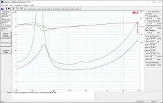
Hi Dave, I have fond memories of camping in your yard! I was one of the three Dana's. I haven't measured anything in two months. I had to hunt around to find cables, drivers, PC and ... I don't have another piece of steel pipe, so here's one with plastic pipe. Red Curve: 2" Whisper Driver A free air. Has a bump at 1500 Hz or so. Blue Curve: 2" Whisper Driver B with fiberglass stuffed 18" long 1.5" ID pipe attached. I will try to measure the metal pipe in the baffle later. I think it will look the same as the plastic pipe.
What does the impedance look like? Both the driver in the TL & in free air?
dave
Hi Dave, I have fond memories of camping in your yard! I was one of the three Dana's. I haven't measured anything in two months. I had to hunt around to find cables, drivers, PC and ... I don't have another piece of steel pipe, so here's one with plastic pipe. Red Curve: 2" Whisper Driver A free air. Has a bump at 1500 Hz or so. Blue Curve: 2" Whisper Driver B with fiberglass stuffed 18" long 1.5" ID pipe attached. I will try to measure the metal pipe in the baffle later. I think it will look the same as the plastic pipe.
Attachments
Impedance
Dave, I found a measurement from last year of the combine six midranges mounted in baffle with fiberglass stuffed 6" steel pipes as shown in the build. I learned how to import the old .zma file and compare with the new measurement. Red Curve: open air. Blue Curve: Six midranges in a series/parallel arrangement. Three parallel sets of two in series. So impedance of group is lower than a single driver.
Dave, I found a measurement from last year of the combine six midranges mounted in baffle with fiberglass stuffed 6" steel pipes as shown in the build. I learned how to import the old .zma file and compare with the new measurement. Red Curve: open air. Blue Curve: Six midranges in a series/parallel arrangement. Three parallel sets of two in series. So impedance of group is lower than a single driver.
Attachments
- Home
- Loudspeakers
- Multi-Way
- System Pictures & Description