This project has been a long time coming, and I hope it can be of interest to some of you out there. I’m happy for all comments, views, questions and suggestions.
As long ago as back in 1984, I came across an article in Hifi News & Record Review about Wharfedale’s Option One research project. Their chief engineer G P Millard investigated the possibility to use dipolar speakers to increase the sweet spot area for stereo listening. This opened my curiosity towards dipolar speakers.
Born and living in Sweden with a burning interest in sound reproduction, you will likely come across the late great speaker designer Stig Carlsson and his unconventional designs. He pioneered a lot of work on how the speakers should be designed in order to interact with a normal living room to create a believable lifelike reproduction of recorded sound, together with the likes like Roy Allison, Peter Snell, Jim Thiel, Harold Beverage and others.
He named his principals ortho acoustics and has been a huge inspiration to my own designs. And since the HNRR article in 1984 I have also been experimenting with dipolar applications to these ortho acoustic design ideas.
A number of incarnations have seen the surface since 1984, some realized and some just ending up as great ideas for the round archive. Then family and career came in between. Eventually this specific revision of my designs was initiated in 2009, when a faulty amplifier (my own modification) literary put the preceding version on fire in its premier listening session. A very sad day in my DIY life, but good things eventually came out of it (I think).
My vision for these speakers was to build a design which interacts positively with the acoustical attributes in a normal living room, in order to create a balanced and lifelike reproduction of a recorded sound - a believable gestalt of the original event. As in the article from 1984 I also wanted to use the dipolar directivity for time intensity trading in order to increase the sweet spot area for believable soundstage reproduction.
My aim was to create a speaker with an even frequency response both for the direct and reflected sound using conventional placement in a normal living room, with controlled directivity and integrated damping to suppress early reflections from influencing the direct sound but still to illuminate the room for a lifelike apparent source width and sensation of envelopment.
The design prerequisites:
- Dipolar speaker using dynamic drivers
- Should work as intended with conventional placement in a normal living space
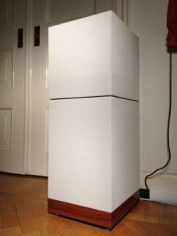
- Discreet design, i.e. family acceptance
We eventually agreed on a design with approximate dimensions of 12x12x34 inches. Which created a lot of folding and puttering on my behalf, but in the end I had an idea of how they should look and how they should be built.
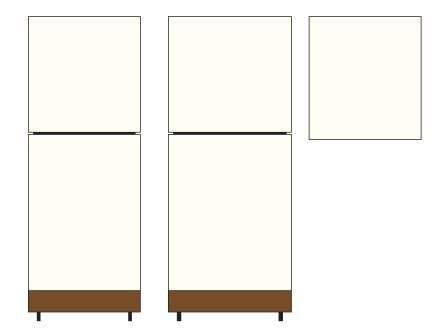
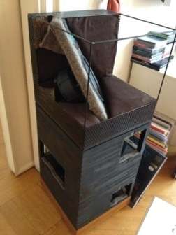
Discreet external design.
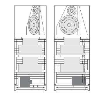
The inside in cross-sections.
That gave me place for two 10” bass drivers in a W-baffle, one 8” midrange unit on an angled baffle with two 1” tweeters on top in dipolar fashion. My idea was to build the whole chassis in layers of routed MDF boards.
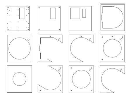
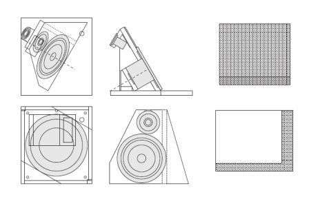
Then you end up with a lot of details like this.
The original intention was to use a professional workshop CNC-cutting all these details, but that plan fell through. So I ended up working with my own hand router (a lot). In hindsight a bad idea. Plain too many hours spent and too much router dust for recommending to anyone else - you are warned. Next speaker will have to be of a different design.
Driver selection fell on:
- two Acoustic Elegance Dipole 10 for bass
- a Seas Excel W22NY001 as midrange
- the Scanspeak Illuminator D3004/660000 and D3004/602010 as tweeters
That would make it possible to reach 110 dB @ 1 meter within linear excursion limits for the intended crossover frequencies and given baffle dimensions.
To be continued.
As long ago as back in 1984, I came across an article in Hifi News & Record Review about Wharfedale’s Option One research project. Their chief engineer G P Millard investigated the possibility to use dipolar speakers to increase the sweet spot area for stereo listening. This opened my curiosity towards dipolar speakers.
Born and living in Sweden with a burning interest in sound reproduction, you will likely come across the late great speaker designer Stig Carlsson and his unconventional designs. He pioneered a lot of work on how the speakers should be designed in order to interact with a normal living room to create a believable lifelike reproduction of recorded sound, together with the likes like Roy Allison, Peter Snell, Jim Thiel, Harold Beverage and others.
He named his principals ortho acoustics and has been a huge inspiration to my own designs. And since the HNRR article in 1984 I have also been experimenting with dipolar applications to these ortho acoustic design ideas.
A number of incarnations have seen the surface since 1984, some realized and some just ending up as great ideas for the round archive. Then family and career came in between. Eventually this specific revision of my designs was initiated in 2009, when a faulty amplifier (my own modification) literary put the preceding version on fire in its premier listening session. A very sad day in my DIY life, but good things eventually came out of it (I think).
My vision for these speakers was to build a design which interacts positively with the acoustical attributes in a normal living room, in order to create a balanced and lifelike reproduction of a recorded sound - a believable gestalt of the original event. As in the article from 1984 I also wanted to use the dipolar directivity for time intensity trading in order to increase the sweet spot area for believable soundstage reproduction.
My aim was to create a speaker with an even frequency response both for the direct and reflected sound using conventional placement in a normal living room, with controlled directivity and integrated damping to suppress early reflections from influencing the direct sound but still to illuminate the room for a lifelike apparent source width and sensation of envelopment.
The design prerequisites:
- Dipolar speaker using dynamic drivers
- Should work as intended with conventional placement in a normal living space
- Discreet design, i.e. family acceptance
We eventually agreed on a design with approximate dimensions of 12x12x34 inches. Which created a lot of folding and puttering on my behalf, but in the end I had an idea of how they should look and how they should be built.
Discreet external design.
The inside in cross-sections.
That gave me place for two 10” bass drivers in a W-baffle, one 8” midrange unit on an angled baffle with two 1” tweeters on top in dipolar fashion. My idea was to build the whole chassis in layers of routed MDF boards.
Then you end up with a lot of details like this.
The original intention was to use a professional workshop CNC-cutting all these details, but that plan fell through. So I ended up working with my own hand router (a lot). In hindsight a bad idea. Plain too many hours spent and too much router dust for recommending to anyone else - you are warned. Next speaker will have to be of a different design.
Driver selection fell on:
- two Acoustic Elegance Dipole 10 for bass
- a Seas Excel W22NY001 as midrange
- the Scanspeak Illuminator D3004/660000 and D3004/602010 as tweeters
That would make it possible to reach 110 dB @ 1 meter within linear excursion limits for the intended crossover frequencies and given baffle dimensions.
To be continued.
Have you seen this site on Stig's work:
CarlssonPlanet.com • Everything about the Carlsson loudspeakers
There was a decent paper covering his theories here:
CarlssonPlanet.com • Downloads
CarlssonPlanet.com • Everything about the Carlsson loudspeakers
There was a decent paper covering his theories here:
CarlssonPlanet.com • Downloads
Pete,
Thanks for posting links to the Carlssonplanet site, and to the paper on some of his design ideas. Well known for all the Carlsson enthusiasts in Sweden.
The wealth of information and experiences on open baffle speakers applications found at the sites of Siegfried Linkwitz and John Krekovsky have also been of great support and inspiration for me in this endeavour.
/Mats
I hope you know these papers:
http://decoy.iki.fi/dsound/ambisoni...udspeaker directional patterns_Kates_1980.pdf
http://www.extra.research.philips.com/hera/people/aarts/RMA_papers/aar03c.pdf
This is a comparison of radiation patterns at 1 kHz for my own dipole and Earl Geddes' Abbey WG loudspeaker:

Geddes is reporting a significantly larger sweet spot with his Abbey speakers while I can't report that for my dipoles in a comparable listening situation. "markus76" is missing this effect in his Nathan speakers (Abbey-like but smaller size) too.
It looks like you need a higher directivity for this effect than a pure dipole will achieve.
You will be interested in the software which Earl Geddes is developing for the control of sweet-spot-enlarging, documented in this thread:
http://www.diyaudio.com/forums/multi-way/231538-new-study-loudspeaker-placement.html
Rudolf
http://decoy.iki.fi/dsound/ambisoni...udspeaker directional patterns_Kates_1980.pdf
http://www.extra.research.philips.com/hera/people/aarts/RMA_papers/aar03c.pdf
This is a comparison of radiation patterns at 1 kHz for my own dipole and Earl Geddes' Abbey WG loudspeaker:
Geddes is reporting a significantly larger sweet spot with his Abbey speakers while I can't report that for my dipoles in a comparable listening situation. "markus76" is missing this effect in his Nathan speakers (Abbey-like but smaller size) too.
It looks like you need a higher directivity for this effect than a pure dipole will achieve.
You will be interested in the software which Earl Geddes is developing for the control of sweet-spot-enlarging, documented in this thread:
http://www.diyaudio.com/forums/multi-way/231538-new-study-loudspeaker-placement.html
Rudolf
I hope you know these papers:
http://decoy.iki.fi/dsound/ambisoni...udspeaker directional patterns_Kates_1980.pdf
http://www.extra.research.philips.com/hera/people/aarts/RMA_papers/aar03c.pdf
This is a comparison of radiation patterns at 1 kHz for my own dipole and Earl Geddes' Abbey WG loudspeaker:
View attachment 334702
Geddes is reporting a significantly larger sweet spot with his Abbey speakers while I can't report that for my dipoles in a comparable listening situation. "markus76" is missing this effect in his Nathan speakers (Abbey-like but smaller size) too.
It looks like you need a higher directivity for this effect than a pure dipole will achieve.
You will be interested in the software which Earl Geddes is developing for the control of sweet-spot-enlarging, documented in this thread:
http://www.diyaudio.com/forums/multi-way/231538-new-study-loudspeaker-placement.html
Rudolf
I've tried it with an 8" full range driver too (Visaton B200). Didn't work either.
By the way, do you have more polars comparing your speaker to the Abbey at different frequencies?
Rudolf,
Thanks for the links and your comments. Yes, the Kates paper is known and I have tracked the theory back to a AES paper by Bauer in 1960 on "Broadening the Area of Stereophonic Perception".
I also realise the dipolar directivity pattern is an approximation of the time intensity trading function investigated in these papers. Maybe you can achieve better correlation with a constant directivity waveguide, but I like to keep it simple and have found the dipolar pattern to be good enough for my aims. I'm reasonably satisfied with the stability in stereo perception through my speakers as I move around in the listening room.
And as Mr. Geddes mentions himself as an issue with waveguide solutions, I rather take advantage of the fair consistency in the polar response for a dipolar speaker throughout the full frequency range. Which helps an eveness in the perceived sound as you move around, as well as it enlightens the room with reflections for a balanced perception of apparent source width and envelopment. This has been very important for me in my designs, and I have prioritised this attribute over an improved match in the time intensity trading function in my speakers so far.
Rgds, Mats
My current project in progress is an OB similar to SL and JohnK designs.
I have 10" woofers, 8" mid, and Neo3 as tweeter.
I have been experimenting with waveguides on Neo3 as well.
I am also considering trying Neo8 as a mid too.
Lately, I have been seeing designs here with tilted mids like the Gradient.
It is interesting to me because my last commercial speaker was an Oskar Heil Syrinx.
So can you please explain to me the benefits of such a design?
Wouldn't it cause big problems when switching from a sitting to standing listening position?
And lets say I use neo8 as mid tilted 45 degrees backwards: would it have the same effect of reducing its height?
As you tilt the driver from vertical towards horizontal mode you also tilt its polar response, from a forward beaming position to an upwards beaming position. And hence alsoto a more omnidirectional pattern in the horizontal plane. The goal with my tilt is to decrease the acoustical energy sent towards the floor by aiming the vertical null towards that direction, as well as sending some more energy upwards to enlighten the room with later reflections.
Sure tilting the baffle can cause problems if you don't balance the directional characteristics of your design. But that can happen with a conventional vertical position just as well.
As speaker unit's directional characteristics is set by the size of the active membrane in relation to the reproduced wavelength. Tilting does not affect the size of the membrane, just the direction of the beam as the membrane gets large compared to the reproduced wavelength.
Be sure to check the Neo 8 excursion requirements in your application depending on choosen crossover topology, baffle size and desired maximum sound level. There is a Neo 10 also, which might fit the bill better as a midrange driver in your project.
/Mats
Some experience from the build. To cut the basic MDF boards in the local property market was easy enough. Loading the trunk of my car with all the bits and pieces I could sense these beasts would be heavyweights by the end of it. Final speaker weights in at roughly 150 pounds each. Huge drawback when you are curious to test and try them out in various surroundings... Next model will have to be lighter.
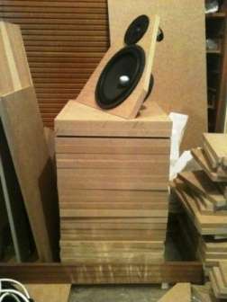
And piling them up to get a first impression of the expected result was smooth. In the pictures I have also cut and routed the first mid baffle.
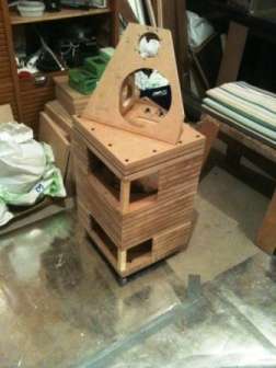
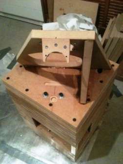
60 routed boards later – phew... Lots of plugs, glue and screws later the result looked like this, the finished raw chassis.
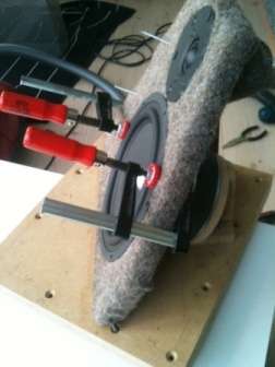
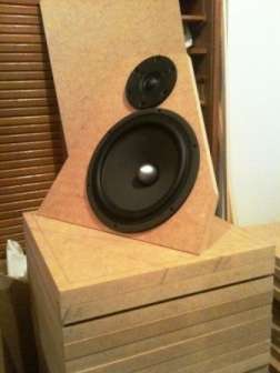
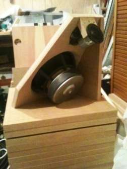
Time to get the drivers in place. The midrange is magnet mounted and this is when I used ferrules to tighten the driver just enough towards the baffle.
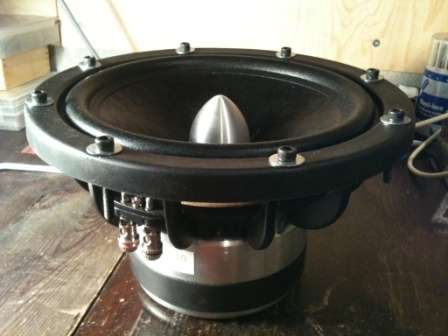
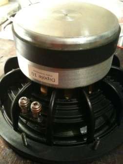
Looks like a huge motor to a diminutive cone on those AE Dipole 10’s. Should be able to keep the bass in control.
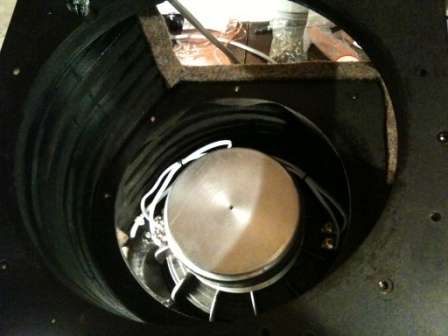
Assembling first the lower and then upper bass driver. The chassis now has some protective paint as well.
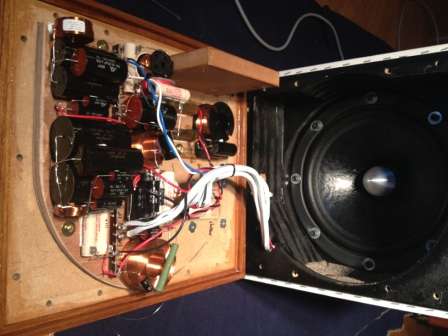
There we go, bass chassis ready with drivers and plinth in place, including one version of a passive crossover.
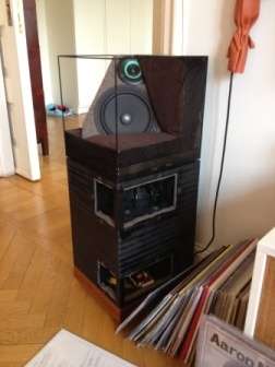
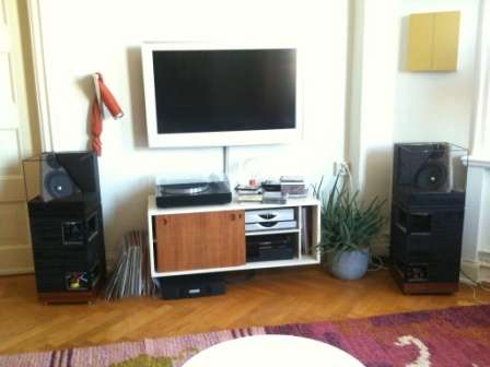
Assembled speakers positioned as intended in the living room.
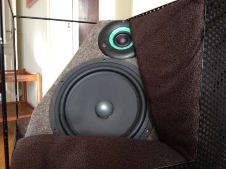
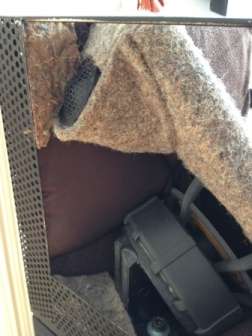
Details on the mid baffle, with damping and an acoustic lens added to the forward Illuminator controlling dispersion.
After my router marathon it was time to focus on the crossover. First I wanted to try out a fully passive solution, but I wasn’t sure I could find a satisfying compromise.
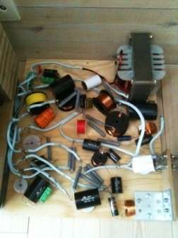
Before you know how it will end up it can look like this…
I made a decision early on to aim for rather steep slopes in the crossover, to ensure the drivers didn’t work outside their linear territory all the way up to anticipated maximum sound level. For the passive version I ended up with LR4 filters at around 300 and 2000 Hz, using the bass drivers all the way up towards the cavity resonance in the W-baffle to avoid burning more than minimum energy in the coil compensating the dipole cancellation. The Seas Excel 8” unit has good dispersion and behaves well enough up to around 2000 Hz, where the tweeters could take over and still manage intended maximum sound levels within their linear region.
Finished passive filters, for bass and midrange in the plinth and the tweeter filters on a detachable tab of the mid baffle.
But I was never fully satisfied with a passive only solution. It would probably have been necessary to filter away a couple of additional decibel sensitivity in order to get the balance just right, and that felt like the wrong way forward. Already as it was, the speakers required a couple of hundred watts to reach maximum intended sound level.
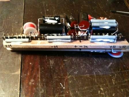
So by now I have turned to a hybrid solution, with active filters between bass and midrange. But keeping the passive filter between midrange and tweeters. The active filter manages compensation for the dipole cancellation and crosses over to the midrange at 150 Hz. I have also rebuilt the passive filters for improved phase correlation in the crossover region. The active filters are based on Linkwitz ASP solution, adapted to my needs.
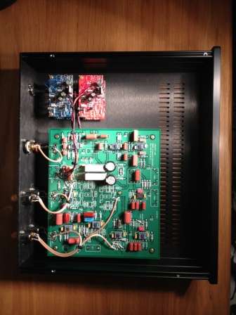
Final filter solution.
Next up – some listening impressions and measurements.
And piling them up to get a first impression of the expected result was smooth. In the pictures I have also cut and routed the first mid baffle.
60 routed boards later – phew... Lots of plugs, glue and screws later the result looked like this, the finished raw chassis.
Time to get the drivers in place. The midrange is magnet mounted and this is when I used ferrules to tighten the driver just enough towards the baffle.
Looks like a huge motor to a diminutive cone on those AE Dipole 10’s. Should be able to keep the bass in control.
An externally hosted image should be here but it was not working when we last tested it.
Assembling first the lower and then upper bass driver. The chassis now has some protective paint as well.
An externally hosted image should be here but it was not working when we last tested it.
There we go, bass chassis ready with drivers and plinth in place, including one version of a passive crossover.
Assembled speakers positioned as intended in the living room.
Details on the mid baffle, with damping and an acoustic lens added to the forward Illuminator controlling dispersion.
After my router marathon it was time to focus on the crossover. First I wanted to try out a fully passive solution, but I wasn’t sure I could find a satisfying compromise.
Before you know how it will end up it can look like this…
I made a decision early on to aim for rather steep slopes in the crossover, to ensure the drivers didn’t work outside their linear territory all the way up to anticipated maximum sound level. For the passive version I ended up with LR4 filters at around 300 and 2000 Hz, using the bass drivers all the way up towards the cavity resonance in the W-baffle to avoid burning more than minimum energy in the coil compensating the dipole cancellation. The Seas Excel 8” unit has good dispersion and behaves well enough up to around 2000 Hz, where the tweeters could take over and still manage intended maximum sound levels within their linear region.
An externally hosted image should be here but it was not working when we last tested it.
Finished passive filters, for bass and midrange in the plinth and the tweeter filters on a detachable tab of the mid baffle.
But I was never fully satisfied with a passive only solution. It would probably have been necessary to filter away a couple of additional decibel sensitivity in order to get the balance just right, and that felt like the wrong way forward. Already as it was, the speakers required a couple of hundred watts to reach maximum intended sound level.
So by now I have turned to a hybrid solution, with active filters between bass and midrange. But keeping the passive filter between midrange and tweeters. The active filter manages compensation for the dipole cancellation and crosses over to the midrange at 150 Hz. I have also rebuilt the passive filters for improved phase correlation in the crossover region. The active filters are based on Linkwitz ASP solution, adapted to my needs.
Final filter solution.
Next up – some listening impressions and measurements.
A little bit about my listening impressions.
I’m really pleased the basic principle works as intended. The stereo image stays between the speakers in a large area of the listening room and does not collapse as you move closer to one speaker. Sure, the stereo image is most natural when you sit in the middle between the speakers, but you still experience a sound stage between the speakers even when you sit right in front of one speaker at normal listening distance. And the sound keeps the same character as you move around in the whole room, which helps both the perception of the direct sound and the reflections.
The wall behind the speakers disappears and the sound stage is built up between, behind, to the outside and above the speakers, depending on the recording. I think it is hard to identify the speakers in the image. My better half says it sounds as for real. And I promise, this is nothing I have ever said she should say to make me happy.
Since the dipolar speaker never will pressurize the room in the same way as a conventional speaker, I have to do without the strong disco punch until I drag in a sub woofer or install a bass shaker to the sofa. Bass is for sure there when it is present in the mix, but never over emphasized or physically overwhelming. Instead, what I get is a very even pitch balance throughout all registers, where I find it simple to follow any instrument or what the musicians are doing irrespective of loud or soft in the mix. And I basically don’t experience any problems with room nodes, standing waves or comb filtering effect from the front wall in my listening room.
The force cancellation between the bass drivers in the W-baffle is also a cool experience. It’s fascinating to see the units pump air at full excursion and the chassis remains completely calm.
Another thing that has surprised me somewhat is that I find it hard to achieve a real sense of loudness from these speakers. Sure, they are not the most sensitive things out there and they need a fair amount of watts in the bass to compensate for the dipole cancellation. But I can in reality measure sound pressures well over 100 dB in my room before my amplifier gives up and it still doesn’t sound loud. I try to still my audiophile diy itch with that this is a good sign of low colouration from my speakers, without a lot of distortion that might give a initial impression of loudness. But tire you long term. What are your experiences around this out there?
I’m very pleased with how the individual drivers perform in my application. I would have appreciated increased sensitivity from the Dipole 10’s to counteract the dipole cancellation, otherwise they perform to my full satisfaction. The Seas Nextel 8” has an edge reflection around 800 Hz which has to be equalized, but still to my ears remains neutral throughout their operating range. The angling puts strong requirements on good dispersion in the upper registers, but I believe the Illuminators and Seas midrange live up to those expectations in my design.
Juhazi,
Sure I have some early reflections from the structures for the backwards projection. But that energy is basically aimed to assist the diffused sound and I'm not too concerned with diffraction effects there as long as the basic balance is ok. Or what do you think?
I believe the frontal projection is reasonably free from disturbing diffractions and early reflections and this is what I have prioritised in this design. At least that is what I interpret in my measurements and what I hear as I listen.
Sondek, I am just a hobbyist. Reflections can't be avoided and by looking at some discussions here at diyaudio, the topic is open and diffuse (sic!)
I am glad that you got the soundfield (-experience) that you wanted!
I have owned a pair of Sonab OA-13 for 15 years now. I know how they sound when placed in various location and environmets. They are now at my summer cabin that has all-wooden structures - the right environment!
In my new dipole project AINO GRADIENT the acoustical room space is different. My side walls are roughly 2m from the speakers. I thin that generally speaking, the room available gives outlines for speaker type and properties, specially sound dispersion patterns (directivity).
Last edited:
Here are some measured results, to illustrate some of my design ambitions. I have found a limited down shelving like on the Linkwitz Orion, roughly -3 dB between 500-5000 Hz, produces the most natural spectral balance for my design as well.
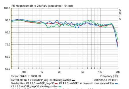
Frequency response gated 3.5 ms. Freefield on axis (red), intended position in room with floor bounce partly damped (blue) and freefield standing (green).
At 3.5 ms gate time the measurement includes the influence from the wall behind the speakers on the direct sound. As you see the response remains in character for the intended room placement, where the integrated damping material and dipolar dispersion pattern helps to reduce the effect of diffraction and early reflections on the direct sound. Green curve is standing position at normal listening distance, so you don’t notice any dramatic change of balance if you sit or stand up during listening.
The effect of dispersion pattern and damping material can be seen even clearer in the next picture, where I compare my design with a conventional reference under the same conditions – freefield versus intended room placement.
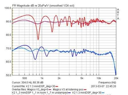
Reference in red and my design in blue. No extra damping used in the room measurement.
The remaining wiggles in the room response are most likely from the residue of the floor bounce, which you can see in the above measurement.
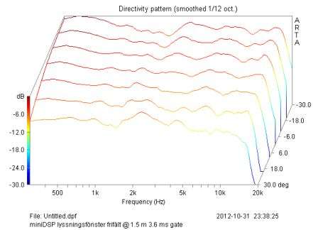
Freefield frequency response for the direct sound within the listening window, where 0 degrees represent on axis listening between the speakers in an equilateral triangle.
The ambition for the direct sound has been to have reasonably similar balance within the listening window between the speakers. The dipolar dispersion helps with the time intensity trading when you move within the listening window and the stereo image remains between the speakers even when you change positions. The biggest compromise is around the crossover frequency at 2 kHz. But I have a hard time to determine which consequence this has on the end result, since the time intensity trading is an approximate psychoacoustic effect for phantom sources already from the start and not a well defined and easily verified quality of any sound source.
A few examples on total sound energy curves in my listening room.
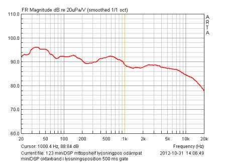
Octave band curve at the listening position with 500 ms gate time.
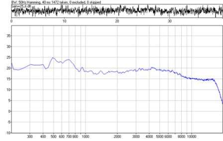
Long term average spectrum curve at the listening position.
Finally some time domain measurements.
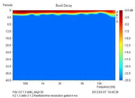
Burst decay free field time resolution gated 4 ms. Freedom of resonances and reflections in the main operating area
My ambition has been to minimize resonances and reflections in the design, by restricting the drivers to work in their linear range and suppress early reflections to not impact the interpretation of the direct sound. And the result can maybe be illustrated by a couple of decay measurements done in the intended position in the living room, compared with measurements on a conventional reference under the same circumstance.
I’m particualarly satisfied with the relative lack of strong early reflections from floor and the wall behind the speakers. The first strong reflex appears more than 8 ms after the direct sound. Earlier reflections are suppressed around 20 dB below the initial transient.
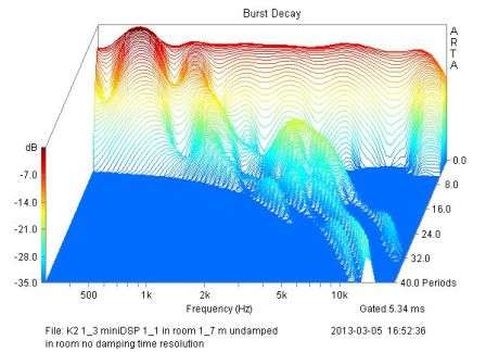
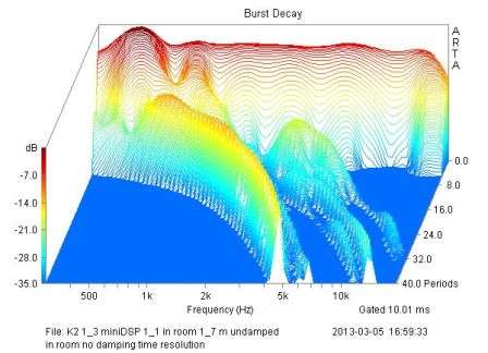
Burst decay at the intended position in a living room, without any additional damping. Reflections are 20 dB below initial pulse.
First strong reflection appears after more than 8 ms in my living room.
For the conventional speaker you can see strong early reflections already after a few milliseconds, with the risk to influence the perception of the direct sound.
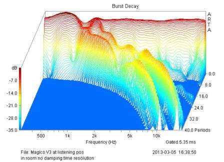
Burst decay at intended position in a listening room without additional damping. Strong early reflections might impact perception of the direct sound.
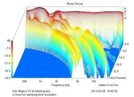
Strong reflections continue after 10 ms.
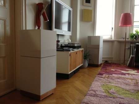
So in the end, after three and a half years, finished speakers in my living room.
Frequency response gated 3.5 ms. Freefield on axis (red), intended position in room with floor bounce partly damped (blue) and freefield standing (green).
At 3.5 ms gate time the measurement includes the influence from the wall behind the speakers on the direct sound. As you see the response remains in character for the intended room placement, where the integrated damping material and dipolar dispersion pattern helps to reduce the effect of diffraction and early reflections on the direct sound. Green curve is standing position at normal listening distance, so you don’t notice any dramatic change of balance if you sit or stand up during listening.
The effect of dispersion pattern and damping material can be seen even clearer in the next picture, where I compare my design with a conventional reference under the same conditions – freefield versus intended room placement.
Reference in red and my design in blue. No extra damping used in the room measurement.
The remaining wiggles in the room response are most likely from the residue of the floor bounce, which you can see in the above measurement.
Freefield frequency response for the direct sound within the listening window, where 0 degrees represent on axis listening between the speakers in an equilateral triangle.
The ambition for the direct sound has been to have reasonably similar balance within the listening window between the speakers. The dipolar dispersion helps with the time intensity trading when you move within the listening window and the stereo image remains between the speakers even when you change positions. The biggest compromise is around the crossover frequency at 2 kHz. But I have a hard time to determine which consequence this has on the end result, since the time intensity trading is an approximate psychoacoustic effect for phantom sources already from the start and not a well defined and easily verified quality of any sound source.
A few examples on total sound energy curves in my listening room.
Octave band curve at the listening position with 500 ms gate time.
Long term average spectrum curve at the listening position.
Finally some time domain measurements.
Burst decay free field time resolution gated 4 ms. Freedom of resonances and reflections in the main operating area
My ambition has been to minimize resonances and reflections in the design, by restricting the drivers to work in their linear range and suppress early reflections to not impact the interpretation of the direct sound. And the result can maybe be illustrated by a couple of decay measurements done in the intended position in the living room, compared with measurements on a conventional reference under the same circumstance.
I’m particualarly satisfied with the relative lack of strong early reflections from floor and the wall behind the speakers. The first strong reflex appears more than 8 ms after the direct sound. Earlier reflections are suppressed around 20 dB below the initial transient.
Burst decay at the intended position in a living room, without any additional damping. Reflections are 20 dB below initial pulse.
An externally hosted image should be here but it was not working when we last tested it.
First strong reflection appears after more than 8 ms in my living room.
For the conventional speaker you can see strong early reflections already after a few milliseconds, with the risk to influence the perception of the direct sound.
Burst decay at intended position in a listening room without additional damping. Strong early reflections might impact perception of the direct sound.
Strong reflections continue after 10 ms.
So in the end, after three and a half years, finished speakers in my living room.
Juhazi,
Love your Aino gradient project! What a coincidence we post almost at the same time talking about dipolar/controlled directivity projects with references to Stig Carlsson and Salmi's Gradient work. Looking forward to follow your progress.
I believe my design would fit well into the acoustic properties of your own listening room. It seems just like the kind of space I would like my speakers to sound good in. I also have similar reverberation time curves in my listening room. Would have loved to try it out...
I will post comments to the Aino project in your own thread.
/Mats
I’ve been reflecting a little bit lately, while enjoying music through my speakers. Here are some findings and lessons learned from this open baffle project on Stig Carlsson’s ortho acoustic design ideas.
I believe the basic design idea is definitely worth to continue pursuing, confirmed both in my listening and measurements. To angle the dipoles like Benjamin Bauer suggests in his 1960 AES paper broadens the area for good soundstage perception. Phantom images off axis are of course not as precise as in the dead center, but still gives a clear sense of soundstage width and the images never collapse into the closest speaker.
The angling also directs more of the radiated energy away from the front wall and towards the side walls. This helps to decrease the influence on the direct sound from early front wall reflections and instead focus more sound energy on the side walls for good illumination of the room by later reflections, assisting the sensation of apparent source width and envelopment in the reproduced sound. There is no problem to create a believable reproduction of the original event with conventional placement of the speakers close up against the front wall in my living room.
Another finding is how the open baffle concept gives a more balanced perception of bass than conventional speakers in my living room, where it is always easy to follow all the details in the register without disturbance from room modes and other resonances. My theory is that the dipolar absence of room gain results in a more natural reproduction of bass, more in line with what we experience in a live event which usually takes place in a larger venue and hence is free from audible room gain effects. There is also less boundary gain with normal conventional room placement, since the gain effect is naturally more evenly distributed over frequency due to the +/- controlled directivity dipole nature of the speakers.
I initially thought I would achieve the same boundary gain as for conventional boxed bass drivers in this project, but realized dipolar radiators act differently in that respect when I sat down and worked out the theory properly. Which led to the decision – the lack of bass sensitivity in my design requires active bass equalization for a proper overall balance in this system. If you aim for a fully passive open baffle system you need really large panels and loads of radiating surface, which ends up in a domestically unacceptable solution for my situation. For the time being I will stick with active solutions in my projects, which also has other advantages to be exploited and some drawback as well. You can’t have it all.
Two additional things in this project have given me new insights. First is how freedom from distortion reduces cues to sensation of loudness. These speakers sound very much the same all the way up in level until the power amplifiers start clipping or audible feedback in the turntable is heard through the system. It just doesn’t sound loud as you increase the volume. It’s not until someone starts to speak or another sound enters the room you realize the how loud the sound is. Sure, you have a level where the reproduction sounds most natural, but it never sounds loud. Almost like the speakers lack dynamics.
The other thing is how sensitive voicing mid and tweeter levels are to get just the right balance in the sound. Often the adjustments are fractions of a decibel between sounding natural or giving you a sensation of some kind of exaggeration. Changes often smaller than what I believe you find in normal sample variation between speaker units. You wonder how commercial speaker manufactures manages their QA.
Finally I want to mention what a great development tool the miniDSP solution is. So much plug’n play capabilities and it makes it dead easy to evaluate design changes with just a flick of a switch. But my analog active filter improves the resolution substantially. The miniDSP is great for the design process, but I will stick with active filter for the final implementation until I find a completely transparent DSP solution.
… and then some ideas possibly worth exploring in forthcoming designs:
- How can I reduce midrange and tweeter bloom to improve dispersion uniformity even further? Possibly investigate alternative baffle structures and waveguide solutions.
- The tilted baffle structure in this design results in reflections affecting the measured direct sound of the back radiation. What happens with a solution with a more uniform measured direct sound?
- What happens with improved physical time alignment between the units?
- How can woofer sensitivity be improved without scarifying other parameters for dipolar designs and still find its way into a domestically accepted solution? Current design requires more power for the lowest frequencies than I have available, to reach the intended maximum sound level. Should investigate alternative drivers, loading and amplifier technologies.
- Further investigations into W-baffle calculation and equalization – cavity dimensions, loading and resonances.
- And next project must be lighter and easier to build.
I repost this post due to a broken link to one of the pictures above.
Here are some measured results, to illustrate some of my design ambitions. I have found a limited down shelving like on the Linkwitz Orion, roughly -3 dB between 500-5000 Hz, produces the most natural spectral balance for my design as well.
Frequency response gated 3.5 ms. Freefield on axis (red), intended position in room with floor bounce partly damped (blue) and freefield standing (green).
At 3.5 ms gate time the measurement includes the influence from the wall behind the speakers on the direct sound. As you see the response remains in character for the intended room placement, where the integrated damping material and dipolar dispersion pattern helps to reduce the effect of diffraction and early reflections on the direct sound. Green curve is standing position at normal listening distance, so you don’t notice any dramatic change of balance if you sit or stand up during listening.
The effect of dispersion pattern and damping material can be seen even clearer in the next picture, where I compare my design with a conventional reference under the same conditions – freefield versus intended room placement.
Reference in red and my design in blue. No extra damping used in the room measurement.
The remaining wiggles in the room response which you can see in the above measurement are most likely from the residue of the floor bounce reflection.
Freefield frequency response for the direct sound within the listening window, where 0 degrees represent on axis listening between the speakers in an equilateral triangle.
The ambition for the direct sound has been to have reasonably similar balance within the listening window between the speakers. The dipolar dispersion helps with the time intensity trading when you move within the listening window and the stereo image remains between the speakers even when you change positions. The biggest compromise is around the crossover frequency at 2 kHz. But I have a hard time to determine which consequence this has on the end result, since the time intensity trading is an approximate psychoacoustic effect for phantom sources already from the start and not a well defined and easily verified quality of any sound source.
A few examples on total sound energy curves in my listening room.
Octave band curve at the listening position with 500 ms gate time.
Long term average spectrum curve at the listening position.
Finally some time domain measurements.
Burst decay free field time resolution gated 4 ms. Freedom of resonances and reflections in the main operating area
My ambition has been to minimize resonances and reflections in the design, by restricting the drivers to work in their linear range and suppress early reflections to not impact the interpretation of the direct sound. And the result can maybe be illustrated by a couple of decay measurements done in the intended position in the living room, compared with measurements on a conventional reference under the same circumstance.
I’m particualarly satisfied with the relative lack of strong early reflections from floor and the wall behind the speakers. The first strong reflex appears more than 8 ms after the direct sound. Earlier reflections are suppressed around 20 dB below the initial transient.
Burst decay at the intended position in a living room, without any additional damping. Reflections are 20 dB below initial pulse.
First strong reflection appears after more than 8 ms in my living room as placed in the picture below.
For the conventional speaker you can see strong early reflections already after a few milliseconds, with the risk to influence the perception of the direct sound.
Burst decay at intended position in a listening room without additional damping. Strong early reflections might impact perception of the direct sound.
Strong reflections continue after 10 ms.
So in the end, after three and a half years, finished speakers in my living room.
Here are some measured results, to illustrate some of my design ambitions. I have found a limited down shelving like on the Linkwitz Orion, roughly -3 dB between 500-5000 Hz, produces the most natural spectral balance for my design as well.

Frequency response gated 3.5 ms. Freefield on axis (red), intended position in room with floor bounce partly damped (blue) and freefield standing (green).
At 3.5 ms gate time the measurement includes the influence from the wall behind the speakers on the direct sound. As you see the response remains in character for the intended room placement, where the integrated damping material and dipolar dispersion pattern helps to reduce the effect of diffraction and early reflections on the direct sound. Green curve is standing position at normal listening distance, so you don’t notice any dramatic change of balance if you sit or stand up during listening.
The effect of dispersion pattern and damping material can be seen even clearer in the next picture, where I compare my design with a conventional reference under the same conditions – freefield versus intended room placement.

Reference in red and my design in blue. No extra damping used in the room measurement.
The remaining wiggles in the room response which you can see in the above measurement are most likely from the residue of the floor bounce reflection.

Freefield frequency response for the direct sound within the listening window, where 0 degrees represent on axis listening between the speakers in an equilateral triangle.
The ambition for the direct sound has been to have reasonably similar balance within the listening window between the speakers. The dipolar dispersion helps with the time intensity trading when you move within the listening window and the stereo image remains between the speakers even when you change positions. The biggest compromise is around the crossover frequency at 2 kHz. But I have a hard time to determine which consequence this has on the end result, since the time intensity trading is an approximate psychoacoustic effect for phantom sources already from the start and not a well defined and easily verified quality of any sound source.
A few examples on total sound energy curves in my listening room.

Octave band curve at the listening position with 500 ms gate time.

Long term average spectrum curve at the listening position.
Finally some time domain measurements.

Burst decay free field time resolution gated 4 ms. Freedom of resonances and reflections in the main operating area
My ambition has been to minimize resonances and reflections in the design, by restricting the drivers to work in their linear range and suppress early reflections to not impact the interpretation of the direct sound. And the result can maybe be illustrated by a couple of decay measurements done in the intended position in the living room, compared with measurements on a conventional reference under the same circumstance.
I’m particualarly satisfied with the relative lack of strong early reflections from floor and the wall behind the speakers. The first strong reflex appears more than 8 ms after the direct sound. Earlier reflections are suppressed around 20 dB below the initial transient.

Burst decay at the intended position in a living room, without any additional damping. Reflections are 20 dB below initial pulse.
First strong reflection appears after more than 8 ms in my living room as placed in the picture below.
For the conventional speaker you can see strong early reflections already after a few milliseconds, with the risk to influence the perception of the direct sound.

Burst decay at intended position in a listening room without additional damping. Strong early reflections might impact perception of the direct sound.

Strong reflections continue after 10 ms.


So in the end, after three and a half years, finished speakers in my living room.

To angle the dipoles like Benjamin Bauer suggests in his 1960 AES paper broadens the area for good soundstage perception. Phantom images off axis are of course not as precise as in the dead center, but still gives a clear sense of soundstage width and the images never collapse into the closest speaker.
There's a paper by Kates which gives a very precise description how the optimum radiation pattern utilizing "trading" should look like: Kates, "Optimum Loudspeaker Directional Patterns", JOURNAL OF THEAUDIO ENGINEERING SOCIETY, 1980 NOVEMBER, VOLUME 28, NUMBER 11
- Status
- This old topic is closed. If you want to reopen this topic, contact a moderator using the "Report Post" button.
- Home
- Loudspeakers
- Multi-Way
- My open baffle project on ortho acoustic design ideas