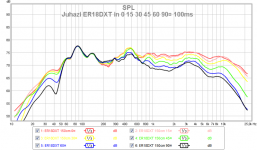
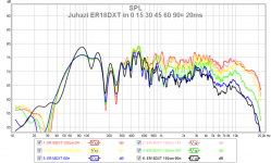
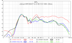
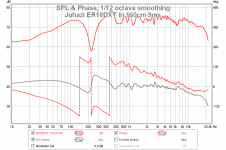
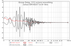
Juhazi ER18DXT dispersion measurements
Attachments
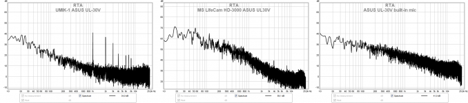
My UMIK-1 is defective 
I tested it with different cables, ports and computers. Ditto. I must send a message about this to miniDSP folks. However I believe that my measurements are ok.
The problems is in the signal processor that is built-in. The level of peaks remains constant regardless of level of "real" noise/sound.
I tested it with different cables, ports and computers. Ditto. I must send a message about this to miniDSP folks. However I believe that my measurements are ok.
The problems is in the signal processor that is built-in. The level of peaks remains constant regardless of level of "real" noise/sound.
Attachments
Last edited:
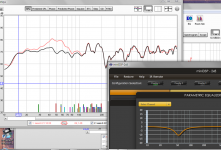
I tamed the peak in bass response, as an excercise because I'm still protoing. Irregularities at 100 to 800 are not so critical because the are not constant at different positions. At least taming them is more complicated, it can't be done with dsp.
By the way - one reason for solid bass might be the high damping factor of a classD amplifier driving the unit without any huge coil between them!
By the way - one reason for solid bass might be the high damping factor of a classD amplifier driving the unit without any huge coil between them!
Attachments
Last edited:
I am still waiting to get bass boxes back from the painter. The weather has bee too windy for outdoor measurements. I've done seome work to get bass integrated to lower mid and this seems to be endless endeavour... I did some major changes to PEQ and xo which resulted in better off-axis behaviour. Indoor mesurements are a pain in the *** below 1kHz because of reflections and difficulty of using short IR time.
My neighbour, the Grammy winner, pianist Marian Petrescu promised to come over and listen to his own recording! I have listened a lot of piano music during this project and I really love the performance of AINO. It is so nice to get a second opinion from the master himself!
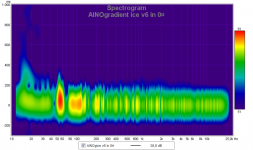
AINO gradient ice v6 indoor measurements
xos 150Hz LR4, 550Hz LR2 and 3100Hz LR4
My neighbour, the Grammy winner, pianist Marian Petrescu promised to come over and listen to his own recording! I have listened a lot of piano music during this project and I really love the performance of AINO. It is so nice to get a second opinion from the master himself!
AINO gradient ice v6 indoor measurements
xos 150Hz LR4, 550Hz LR2 and 3100Hz LR4
Attachments
-
 ainogice v6 in decay spectr.png191.7 KB · Views: 65
 -
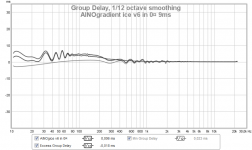 ainogice v6in0¤ gd 9ms.png41.3 KB · Views: 81
 -
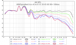 ainogice v6 in 0 15 30 45 60 90¤ 100ms 13.png80.1 KB · Views: 75
 -
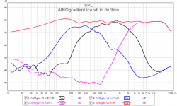 ainogice v6 in 0¤ all indiv 9ms 13.png63.6 KB · Views: 71
 -
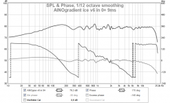 ainogice v6 in 9ms 0¤ spl phase 112.png60.9 KB · Views: 88
 -
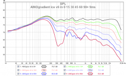 ainogice v6 in 0 15 30 45 60 90¤ 9ms 13.png77.7 KB · Views: 2,625
Last edited:
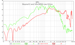
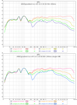
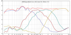
I measured raw responses of the Beyma 12MWNd and Vife NE95 pair, installed in the pole of AINO, on top of the proto bass box. The dip in Beyma's response at 150Hz is floor reflection.
The dipole null of Beyma is 1,2kHz and it was too close to the xo previously. Vifa pair can easily go lower. I moved xo from around 1000Hz to ~580Hz in v6
The dipole null of Beyma is 1,2kHz and it was too close to the xo previously. Vifa pair can easily go lower. I moved xo from around 1000Hz to ~580Hz in v6
Attachments
Last edited:
It was a nice and quiet evening - I did some adjustments and ended with v61.
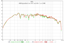
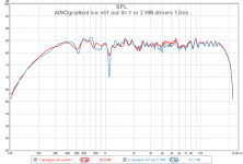
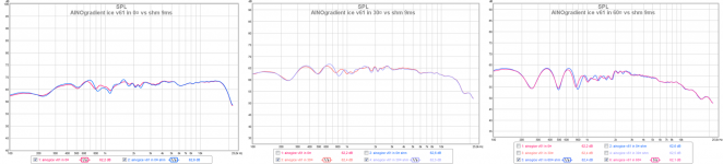
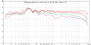
AINOgradient ice v61 highlights from the outdoor measurement session (without W)
AINOgradient ice v61 highlights from the outdoor measurement session (without W)
Attachments
-
 ainogice v61 out 60¤ 1 or 2 hm.png56.7 KB · Views: 573
 -
 ainogice v61 ut 0¤ 1 or 2 hm.png54.6 KB · Views: 560
 -
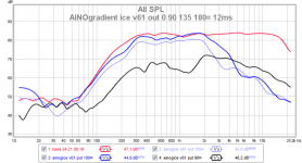 ainogice v61 put 0 90 135 180¤ 12ms 13.png65.3 KB · Views: 78
 -
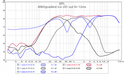 ainogice v61 out 0¤ all indiv inv 12ms 13.png76.9 KB · Views: 361
 -
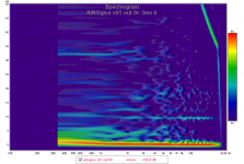 ainogice v61 out decay spec 3ms.png290.1 KB · Views: 61
 -
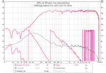 ainogice v61 out 0¤ spl phase 9ms nosmo.png91.2 KB · Views: 75
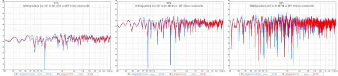
I am on a summer vacation and I had some spare time to do more measurments of MTM vs MT arrangement, using my AINOgradient ice as a test mule. Sorry, I had to use low level.
CharlieLaub is a honored person among diyers. He critisized using a MTM arrangement in dipoles. I disagree and tried my best to find out measurements/data to give light to the topic. I must say that a MTM is better in my AINOgradient in every respect, accodring these measurements. Theory and Charlie's experience may be different.
I measured inside, speaker in the middle of the room, mic at 150cm distance, at tweeter height (when stated low at lower mid's height).
First horizontal directivity with 9 and 200ms IR window
- MTM is better
Attachments
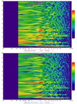
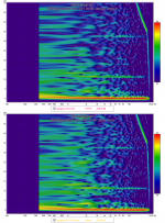
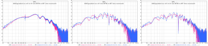
Reflections, spectral decay
- look close at range 1 to 3 kHz
- not a big difference but mtm looks better to me (less red areas in short time)
- look close at range 1 to 3 kHz
- not a big difference but mtm looks better to me (less red areas in short time)
Attachments
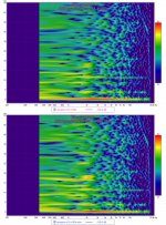
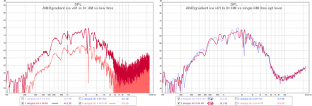
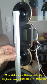
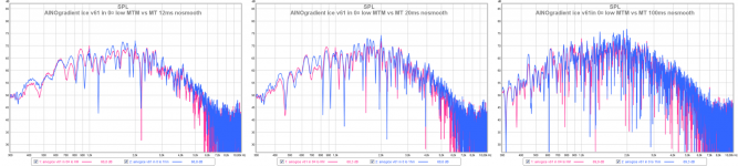
Vertical variations - comb filtering?
I took measurement at tweeter height and at lower mid's height (low) - 95mm lower. Distance from mids' center to center is 190mm (7½")
Only some comparisons shown here.
- to me it looks like a single mid has more variations both on-level and of-level vertically. I can see some comb filtering though for MTM arrangement measured at lower mid's height.
Finally - I chose MTM because I was afraid that I would stress a single 3" mid driver too much with the extensive shelving for dipole loss at the low end, distortion wise (LR2). I don't trust my measuring talent enough to do and show reliable distortion measurements - my environment is too noisy for that. A sigle M is used in most of latest dipoles by guys that used double mids earlier (LX521, NoO NoteII) One reason that made this possible is to change from a 3-way to 4-way. The main reason for a 4-way is to extend dipole function higher by a more narrow baffle (and a smaller diameter driver)
Attachments
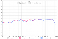
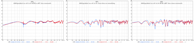
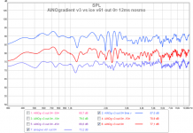
Looking for comb filtering - closeups with no smoothing
MTM red
MT blue
Measured at tweeter height 100cm to floor, 150cm distance
Low (only highmid playing) measured ~90cm to floor, at lower mid's height, 150cm distance
--> I can't find a flaw in MTM setup
MTM red
MT blue
Measured at tweeter height 100cm to floor, 150cm distance
Low (only highmid playing) measured ~90cm to floor, at lower mid's height, 150cm distance
--> I can't find a flaw in MTM setup
Attachments
-
 ainogice v61 in 0¤ mtm vs mt close 12ms nosmo-horz.png345.5 KB · Views: 462
 -
 ainogice v61 in 0¤ mtm vs mt close 2ms nosmo-horz.png168.4 KB · Views: 501
 -
 ainogice v61 in 0¤ low mtm vs mt close 2ms nosmo-horz.png216.8 KB · Views: 450
 -
 ainogice v61 in 0¤ low mtm vs mt close 12ms nosmo-horz.png378.7 KB · Views: 448
Last edited:
Here is a thread about lobing and comb filtering. It happens in every multidriver system with any amount of overlapping frequencies at xo. Theoretically also in a single transducer's membrane from edge to edge. The critical limit is generally 1/4 of wave length:
Center to center distance/ unified wavefront limit/ first major comb freq range
8"/ 1800 Hz/ 3200 Hz
6"/ 2300 Hz/ 4100 Hz
4"/ 3600 Hz/ 7000 Hz
We must remember that cf lobing happens same plane as the drivers are. Lobing "density" gets greater with distance and smaller with frequency. One can hear it easily when playing a sine wave and moving around in the room. Surface reflections cause comb filtering too but in a more compex way. We can see the effects of this in measurement as "nulls" in amplitude response graphs. When lookin at these we must remember that they are spesific to certain distance and angulation to the source. Also when measuring the time window used makes them look different.
Basics of waves and interferencies is expaned with animations here by Dr. Dan Russell
and here is a interference simulator http://serc.carleton.edu/NAGTWorkshops/deepearth/activities/40826.html
This is perhaps the best animation of a two-source interference http://www.acoustics.salford.ac.uk/feschools/waves/super2.htm
Last edited:
Looking for comb filtering - closeups with no smoothing
MTM red
MT blue
Measured at tweeter height 100cm to floor, 150cm distance
Low (only highmid playing) measured ~90cm to floor, at lower mid's height, 150cm distance
--> I can't find a flaw in MTM setup
That's because you are not looking in the right place!
MTM response "flaws" are found "off axis" in the plane formed by a line connecting the centers of the two woofers (e.g. vertical plane). Take some vertical plane off axis measurements out to 30 degrees to discover the "problem areas".
You can predict what you will see using TheEdge, for closed or open baffles. It's very useful for this purpose.
-Charlie
Using the numbers that you quoted for the unified wavefront limit...
For instance, using a 5.25 (17cm) midbass and a 1" dome tweeter with a 4" (10cm) flange, the center-to-center distance is 0.5*(17+10)=13.5cm (about 5.25"). You can cross a modern, robust tweeter as low as 1.5kHz. According to your info, a driver that is 6" apart will have a unified wavefront up to 2300Hz, so there is about an octave between the crossover point and where the wavefront starts to develop lobing. This allows the midwoofer response to be sufficiently attenuated and lobing is not a problem. It's all good!
-Charlie
...it is easy to see how to design a multi-way system that does not have lobing problems. If you cross over from midrange/woofer to the tweeter at a relatively low frequency and locate the driver centers as close together as possible you can easily meet the criteria for a "unified wavefront".Center to center distance/ unified wavefront limit/ first major comb freq range
8"/ 1800 Hz/ 3200 Hz
6"/ 2300 Hz/ 4100 Hz
4"/ 3600 Hz/ 7000 Hz
For instance, using a 5.25 (17cm) midbass and a 1" dome tweeter with a 4" (10cm) flange, the center-to-center distance is 0.5*(17+10)=13.5cm (about 5.25"). You can cross a modern, robust tweeter as low as 1.5kHz. According to your info, a driver that is 6" apart will have a unified wavefront up to 2300Hz, so there is about an octave between the crossover point and where the wavefront starts to develop lobing. This allows the midwoofer response to be sufficiently attenuated and lobing is not a problem. It's all good!
-Charlie
There is a way to "win" vertical lobing - CBT arrangement by Don Keele! Don Keele's CBT (Constant Beamwidth Transducer) Page When we look at Don's pdf, on page of AudioArtistry, we can see that his cbt compromises on horizontal directivity! I wonder if we could combine exceptional horizontal and vertical directivity and minimal lobing effects?!
We have a definition called "listening window" whre artifacts caused by poor lateral dispersion, comb filtering, edge diffractions etc. are minimal. I chose to have a wide lateral and narrow vertical window.
For AINO I decided to create maximal vertical directivity and uniform/controlled/constant horizontal directivity. I chose a tweeter for that (Fountek NeoCD3.5H) and a MTM configuration with small diameter mids. By cutting the edges of the tweeter I reached M to M center distance of 190mm (7½") The tweeter has loads of distortion from 2500Hz down and it is on the limit here... Also the M-M system is on the limit considering comb filtering. The xo is LR4 at 3000Hz - a compromise with these chosen ones.
As I stated in another thread, this is like cuisine - mixing materials, processing them with skill and flavouring with finesse! Another cook would have chosen different raw materials and recipes! My result is the best I can make with these!
Vertical directivity measurements from a wider angle needs a different measuring setup and a helping pair of hands! Perhaps one day... My angle at the last indoor measurement was -3,5¤. There I can see some comb filtering at 4kHz and higher. The lobes of a single mid are caused by dipole problems above the dipole null!
Last edited:
Charlie et al. - I have shown vertical measurements of AINO earlier http://www.diyaudio.com/forums/mult...aborative-speaker-project-19.html#post3499643
I had saved those measurements and I will postprocess them to look for comb filtering problems (which really exist, no doubt.) But just at first look there are more prominent issues, as can be expected, based on dipole behaviour and 30¤ degree angulation of lower mid. It was one guideline in the design to minimize floor reflections - angulate LM back to make advantage of dipole function and use high-MTM with a highly directive tweeter.
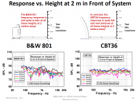
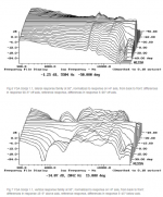
For a reference here is my and Keele's B&W 801 vertical dispersion, taken from Audio Artistry
I had saved those measurements and I will postprocess them to look for comb filtering problems (which really exist, no doubt.) But just at first look there are more prominent issues, as can be expected, based on dipole behaviour and 30¤ degree angulation of lower mid. It was one guideline in the design to minimize floor reflections - angulate LM back to make advantage of dipole function and use high-MTM with a highly directive tweeter.
For a reference here is my and Keele's B&W 801 vertical dispersion, taken from Audio Artistry
Attachments
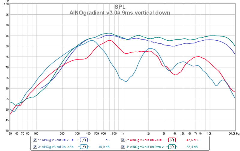
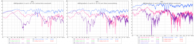
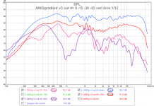
Closeups of vertical dispersion of AINOgradient
Measurements were taken outdoors on lawn (grass), distance 150cm. Microphone handheld for off-axis (degrees are estimates). The v3 had a phase/delay match problem that appears as lobing just above 2kHz. Other than that we can see MTM comb filtering and dipole-typical nulls.
When listening to the speaker indoors I have distance of 2 - 3m (6-9') - floor reflections come from roughly -30 to -45¤ dispersion angle. We can see that these responses are far from even and the effect of vertical comb filtering form the vertical MTM must be a minor problem.
Attachments
Last edited:
I just read the Stereophile review of 107.000$/pair YGA Sonja speakers. The editor said that these are the best he has heard in his 37 years of career. Sonjas have a MTM arrangement and rather similar horizontal and vertical measured responses as my AINOgradient. I guess that the vertical lobing of a MTM is not necessarily a bad thing, considering the benefits it gives.
Attachments
Last edited:
The 51st AES Conference is in Helsinki in August. Finnish members get free access on Wednesday, which is also netcasted Active Loudspeaker Design Masterclass LIVE WEBCAST... Registration, Helsinki - Eventbrite The topic suits me well - designing active speakers!
I will go to Helsinki for this and I willl try to find a way be there also on Thursday to hear and see S Linkwitz.
Program Program AES 51st Conference, Helsinki, Finland, August 21-24, 2013.
I will go to Helsinki for this and I willl try to find a way be there also on Thursday to hear and see S Linkwitz.
Program Program AES 51st Conference, Helsinki, Finland, August 21-24, 2013.
On a rainy day I made some minor mods to crossover and measured a speaker indoors (more than 2m from walls). The painter still has my bass boxes, But now I just wait because I have my summer holidays and we visiting our summer cabin and have all kinds of other activities often.
The bass needs a lot of taming to integrate to the lower mid and when I change the speaker's position in the room, response changes. This is mostly a learning phase for me, before I get the final boxes.
The bass needs a lot of taming to integrate to the lower mid and when I change the speaker's position in the room, response changes. This is mostly a learning phase for me, before I get the final boxes.
Attachments
- Home
- Loudspeakers
- Multi-Way
- Aino gradient - a collaborative speaker project