Thank you for your interest an comments & ideas! This is a long thread with many evolution stages of AINOgradient speakers.
A long story made short about AINOs...
The basic consept is copied from 1980's Jorma Salmi design Gradient 1.x series - a very good review here The Gradient 1.3 Revisited
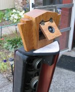
I studied Linkwitz and Kreskowsky homepages and got personally helped by Rudolf Finke. Minidsp and REW made all this possible for me and are key factors in multiway dipoles for dummies! The shape of bass module comes from a very popular glass by Aino Aalto, wife of architect Alvar Aalto. My daughter and grandmother are also named Aino.
Acoustically Ainos are monopole below 100Hz, cardioid 100-300Hz, dipole from up there (highest dipole null around 6kHz) In early stages I struggled with rearside radiation anomalies of cone drivers and reflections from the large magnet of Fountek Neo3.H. These were fixed by using B&G Neo8 and Neo3 planar units. Another great struggle has been indoor measurements, remember the weather here in Scandinavia!
For the last 9 months I have only made minor adjustments in minidsp settings, mainly to optimize acoustic responses of each driver and tonality of the system. I am very happy with the present performance, and so were the people at the Finnish diy-audio event - AINOgradient got the nomination for "Best Sound in the Show"
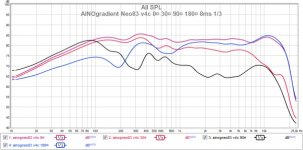
Here indoor-measurements at 1.5m distance. RTA/steady state response in-room is 16Hz -18kHz in a slightly descending (ideal) room curve. The upper end is limited because of Icepower D-class amplifier's input-impedance problem (but my aged ears don't hear that)
A long story made short about AINOs...
The basic consept is copied from 1980's Jorma Salmi design Gradient 1.x series - a very good review here The Gradient 1.3 Revisited
I studied Linkwitz and Kreskowsky homepages and got personally helped by Rudolf Finke. Minidsp and REW made all this possible for me and are key factors in multiway dipoles for dummies! The shape of bass module comes from a very popular glass by Aino Aalto, wife of architect Alvar Aalto. My daughter and grandmother are also named Aino.
Acoustically Ainos are monopole below 100Hz, cardioid 100-300Hz, dipole from up there (highest dipole null around 6kHz) In early stages I struggled with rearside radiation anomalies of cone drivers and reflections from the large magnet of Fountek Neo3.H. These were fixed by using B&G Neo8 and Neo3 planar units. Another great struggle has been indoor measurements, remember the weather here in Scandinavia!
For the last 9 months I have only made minor adjustments in minidsp settings, mainly to optimize acoustic responses of each driver and tonality of the system. I am very happy with the present performance, and so were the people at the Finnish diy-audio event - AINOgradient got the nomination for "Best Sound in the Show"
Here indoor-measurements at 1.5m distance. RTA/steady state response in-room is 16Hz -18kHz in a slightly descending (ideal) room curve. The upper end is limited because of Icepower D-class amplifier's input-impedance problem (but my aged ears don't hear that)
Attachments
Thanks Juhazi for the article on the Aino. I read most of it. Now I can talk more on subject.
The speaker that got me going on open baffle design had two 8 inch drivers with a 1 inch dome tweeter in between them, mounted in a frame that was just two 3 inch side panels, no actual front board, drivers held in by their magnets, and that sat on top of a woofer cabinet. This system also had passive OB EQ, at the expense of system efficiency. For the first five minutes of listening, I didn't know they were open-baffle. I finally went up and peeked through the grill cloth, and said something like, "this can't work"... They created such a good 3-D effect that I immediately started researching how to make the best open baffle speaker system for myself.
Once you've made the decision to do the crossover actively, you've got a chassis with a power supply, which makes it relatively easy to add low end active woofer EQ (which works significantly better with a closed box woofer). It's also easy to add active OB EQ for the midrange driver. One big benefit which this active EQ approach has is that you get your efficiency back.
Taking what looks like a 12 inch driver up to 1.5kHZ means the emission would start to get a bit directional at the top end, which might actually balance well with the limited dispersion at the low end of the mid driver, due to cancellations from diffraction. But I still think I'd go with an 8 inch driver for 250HZ - 1.5kHZ.
Imaging might be noticeably improved if the crossover at 1.5kHZ was 24dB/octave. There would be less interaction between the tweeter outputs and the mid output in that frequency region, which causes max output beam movement, that might interact with room acoustics differently, causing balance issues in the upper mid frequencies, where we get our best stereo effect imaging (since inter-aural crosstalk issues there are minimal).
I love the sound of ribbon tweeters (I've used several different Fountek ribbons and been very pleased), but taking them all the way down to 1.5kHZ might be tricky. Having a small vertical array of them might fix that issue good enough unless you want VERY loud presentations. I love the tilt on the midrange driver, to reduce floor bounce and improve diffusion of the backwave. I tilted my mid drivers (vertical array of four 5 inch drivers) back 10 degrees and put a waveguide behind them to help diffuse the rear output.
The older we get, the less we need tweeters to go all the way to 20kHZ. I figure 15kHZ is enough if the freqs below that are very smooth and low distortion. I use the Seas Millenium 1 inch dome, which have a very neutral and natural sound to them, but don't seem to be quite as clean and pure sounding at the top end as the ribbons. Plus they are very expensive ($230 each). I heard them in the Linkwitz Orion and fell in love with them. The Orion sounded incredible to me from about 100HZ on up, but the bass didn't have a lot of depth. To me, having the bass be somewhat acoustically flat down to 30 HZ is worth it at any expense. The warmth, the sense of immersion, the improved sense of reality at all frequencies due to waveform envelops getting their more true BW.
Ported woofers have poor damping at frequencies other than the tuned frequency, and getting the tuning just right, and stable over time, can be difficult. Because of the poor damping of the woofer cone at the lowest frequencies, active EQ forcing them to be acoustically flat to 30HZ can also make them susceptible to bottoming out (that snap sound when the voice coil hits the bottom of the slot). So I'd definitely recommend a closed box approach for the woofer.
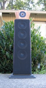
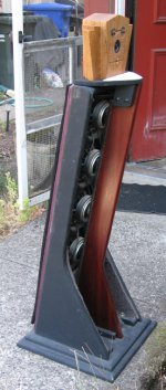
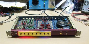
I'll upload a few pictuers of my OB system. The woofers (not shown) are in separate cabinets that can be positioned for better room acoustics interaction. The rear tweeter is only active above about 12kHZ. The triamp's xover Freqs are 100 and 1.4kHZ 4pole. Their weak link is integration if you sit too close. The tweeter sounds a little disconnected. At a distance of 6 ft. or more, it's not a problem, and they sound VERY nice with a good recording. They also work surprisingly well when I switch in my variation of the Carver Holographic Generator, which largely cancels inter-aural crosstalk when you sit right in the middle. Imaging is then wall to wall. I downloaded a bunch of binaural/Blumlein recordings off the web and they work reasonably well too with the Holographic Generator enabled.
The speaker that got me going on open baffle design had two 8 inch drivers with a 1 inch dome tweeter in between them, mounted in a frame that was just two 3 inch side panels, no actual front board, drivers held in by their magnets, and that sat on top of a woofer cabinet. This system also had passive OB EQ, at the expense of system efficiency. For the first five minutes of listening, I didn't know they were open-baffle. I finally went up and peeked through the grill cloth, and said something like, "this can't work"... They created such a good 3-D effect that I immediately started researching how to make the best open baffle speaker system for myself.
Once you've made the decision to do the crossover actively, you've got a chassis with a power supply, which makes it relatively easy to add low end active woofer EQ (which works significantly better with a closed box woofer). It's also easy to add active OB EQ for the midrange driver. One big benefit which this active EQ approach has is that you get your efficiency back.
Taking what looks like a 12 inch driver up to 1.5kHZ means the emission would start to get a bit directional at the top end, which might actually balance well with the limited dispersion at the low end of the mid driver, due to cancellations from diffraction. But I still think I'd go with an 8 inch driver for 250HZ - 1.5kHZ.
Imaging might be noticeably improved if the crossover at 1.5kHZ was 24dB/octave. There would be less interaction between the tweeter outputs and the mid output in that frequency region, which causes max output beam movement, that might interact with room acoustics differently, causing balance issues in the upper mid frequencies, where we get our best stereo effect imaging (since inter-aural crosstalk issues there are minimal).
I love the sound of ribbon tweeters (I've used several different Fountek ribbons and been very pleased), but taking them all the way down to 1.5kHZ might be tricky. Having a small vertical array of them might fix that issue good enough unless you want VERY loud presentations. I love the tilt on the midrange driver, to reduce floor bounce and improve diffusion of the backwave. I tilted my mid drivers (vertical array of four 5 inch drivers) back 10 degrees and put a waveguide behind them to help diffuse the rear output.
The older we get, the less we need tweeters to go all the way to 20kHZ. I figure 15kHZ is enough if the freqs below that are very smooth and low distortion. I use the Seas Millenium 1 inch dome, which have a very neutral and natural sound to them, but don't seem to be quite as clean and pure sounding at the top end as the ribbons. Plus they are very expensive ($230 each). I heard them in the Linkwitz Orion and fell in love with them. The Orion sounded incredible to me from about 100HZ on up, but the bass didn't have a lot of depth. To me, having the bass be somewhat acoustically flat down to 30 HZ is worth it at any expense. The warmth, the sense of immersion, the improved sense of reality at all frequencies due to waveform envelops getting their more true BW.
Ported woofers have poor damping at frequencies other than the tuned frequency, and getting the tuning just right, and stable over time, can be difficult. Because of the poor damping of the woofer cone at the lowest frequencies, active EQ forcing them to be acoustically flat to 30HZ can also make them susceptible to bottoming out (that snap sound when the voice coil hits the bottom of the slot). So I'd definitely recommend a closed box approach for the woofer.
I'll upload a few pictuers of my OB system. The woofers (not shown) are in separate cabinets that can be positioned for better room acoustics interaction. The rear tweeter is only active above about 12kHZ. The triamp's xover Freqs are 100 and 1.4kHZ 4pole. Their weak link is integration if you sit too close. The tweeter sounds a little disconnected. At a distance of 6 ft. or more, it's not a problem, and they sound VERY nice with a good recording. They also work surprisingly well when I switch in my variation of the Carver Holographic Generator, which largely cancels inter-aural crosstalk when you sit right in the middle. Imaging is then wall to wall. I downloaded a bunch of binaural/Blumlein recordings off the web and they work reasonably well too with the Holographic Generator enabled.
Attachments
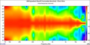
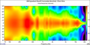
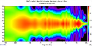
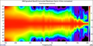
I copied REW measurements as .frd and run horizontal polar graphics in Omnimic software. 8ms gating and 1/6oct smoothing. Some room reflections are included. Notice that scale starts from 70hz! I should roll new polar measurements some day with optimized conditions...
Raw and normalized
Raw and normalized
Attachments
Bob, nice work!
I prefer LR4 acoustic slopes too. I have also LR2 settings in minidsp but then I loose some clarity, obviously from increased intermodulation. The lowest xo is LR2 to make mono-cardiod-dipole radiation changes smoother.
I share your thoughts about closed box bass too. Downfire placement helps me a lot, LR2 at 180Hz makes me localize bass sound to the 12" dipole driver. My single mid driver focuses most instruments nicely in it vertically. My listening distance is roughly 2.5m (8-9ft)
I've been curious about down firing woofers since the early 1960's when Empire made such speakers. The floor being so close would increase damping on the cone, and that may affect what is the best internal volume (?). I would guess that the internal box volume would need to be bigger, so less cone damping from the box, to compensate for the extra damping by the proximity to the floor.Bob, nice work!
I prefer LR4 acoustic slopes too. I have also LR2 settings in minidsp but then I loose some clarity, obviously from increased intermodulation. The lowest xo is LR2 to make mono-cardiod-dipole radiation changes smoother.
I share your thoughts about closed box bass too. Downfire placement helps me a lot, LR2 at 180Hz makes me localize bass sound to the 12" dipole driver. My single mid driver focuses most instruments nicely in it vertically. My listening distance is roughly 2.5m (8-9ft)
My lower midrange vertical array works very well to minimize floor and ceiling bounce, but at the expense of integration with the tweeter on top if you're too close. Not a big problem, but many people prefer the sound of a point source. I tried moving the tweeter down below one of the mid drivers, and didn't like it as well. The tweeter really needs to be at least 3 feet off the floor, and I didn't want the overall baffle height to exceed 45 inches.
The lower db/oct slopes lose clarity not just from intermodulation, but also from how the beams from the two drivers (mid and tweeter, for ex.) add acoustically at and near the crossover frequencies. The phase shift caused by the crossover, causes maximum output beaming to shift over frequency in that region, which can be exasperated by differing room acoustics, or tolerance of crossover parts or speaker driver impedances being loose, causing balance to vary with frequency. Many rooms aren't very symmetrical. Some drivers could have differing impedances at the frequency where the crossover happens. Keeping crossovers out of the 1.5kHZ - 6.5kHZ frequency band seems like one of the best ways to optimize the stereo effect imaging.
My speakers have dual MLTL's subs integrated where the woofers placed midwall ~4' off the floor and against the wall, but the port is coupled to the floor. The wide baffle ~23" (not OB) helps everything above ~200Hz. These create the wings and oppose the MTM section on either side. This realises flanking woofers driven from 4 room points each. GD peaks at 8ms at the bottom end. Works exceedingly well with a bottom end limit of ~26Hz. It'll do an A note (27.5Hz) with aplomb.
I haven't tried this, and made measurements, but I wonder if driving the bass right into the floor for diffusion works better with room acoustics than having the woofer output be as far from room boundaries as is practical, like in the KEF 107 (?).
I noticed that Linkwitz has his woofer at the top of a approx. 3 ft high pipe shaped enclosure in the model LX Mini. As far from a room boundary as was practical. Being an expert on Rf waveguides, he may know more about that.
I like how the KEF 107 has the two woofers shaking the cabinet out of phase, so cabinet vibration distortion is largely cancelled (not sure they needed the rod).
I've been wondering if Something similar to the LX Mini, but with two 8 inch woofers, one at the top and one at the bottom might work better. Stimulating the room at two different places could cause a filling in of one set of comb filter effects by the other woofer, over a certain frequency range, and on the vertical axis. If I ever sell my OB system, I might try that. This technique would also involve cabinet shaking cancellation to a large degree (without the rod). I wondered why KEF went back to front facing woofers and ports after the 107 in the late 1980's. I'm guessing it's because of production costs. It would be interesting to build and measure all 3 variations in typical rooms; floor emission only, top emission only, and then the combination of the two... with the woofers cut off at 300HZ.
I would think KEF would have tried that, and concluded that woofer emission away from room boundaries is actually better (otherwise they might have vented the lower woofer out the bottom). Less boundary reinforcement, but maybe less comb filtering at the listener position. The fact that they chose to run all emissions out the top in the 107, and that Linkwitz did that in the LX Mini causes me to suspect that. If that's true, then maybe doing a 107 or LX Mini with the emission out the front and at the top, might work even better with room acoustics, since it would be less omni, which could be an issue when the speaker is close to walls behind it.
Sorry if I'm getting off subject again.
LXmini has it's bass driver upwards to integrate with midtweeter seamlessly, xo is rather high. It needs subwoofer's help for full range operation.
Multiple woofers in opposite/more sides are very tricky. KEF Blade is not flawless but very good, GET Triton One has passivereflex elements on side walls. DIYers have published some cardioid twin-driver boxes, but I am not convinced if that is worth the effort.
My choice of copying Gradient 1.x arrangement was just simple and even more than that with a closed box! The original is bass-reflex.
Juha, et al, The dual mltl 6.5" / AMT setup I was playing with a couple years ago (and you suggested build it) had to have the cross point lowered due to the extreme off axis angle of the midbasses, but not as much as measurements would suggest. The only reason I could come up with as to why this was came down to near wall reflection and ceiling reflection masking the direct field response. Sound everywhere, nice and ambient but lacked imaging below the crossover point of the AMT on axis. This was why I didnt build... well actually know how to correct (ala Pluto), eg a smaller mid ~5" was required. Simply didnt have the cash to divert from the current project 2.5 years in the making  Heh, at least it did not require a sub at all.
Sub exhibits the three kings in its response, length, width and height room mode peaks when placed this way. Floor bounce is offset due to the mtm.
FYI personally speaking I do not setup speakers in the typical room positions. They are placed midwall away from corners and against the wall. The front baffle exhibits ultra low horizontal diffraction and its width minimizes most major issues down to ~200Hz. Results in a sound field free of normal artifacts BOX speakers always show when placed this way.
P.S. Just installed minidsp's C-DSP 6x8 in a buddys Jeep CK. AWESOME
Heh, at least it did not require a sub at all. Sub exhibits the three kings in its response, length, width and height room mode peaks when placed this way. Floor bounce is offset due to the mtm.
FYI personally speaking I do not setup speakers in the typical room positions. They are placed midwall away from corners and against the wall. The front baffle exhibits ultra low horizontal diffraction and its width minimizes most major issues down to ~200Hz. Results in a sound field free of normal artifacts BOX speakers always show when placed this way.
P.S. Just installed minidsp's C-DSP 6x8 in a buddys Jeep CK. AWESOME
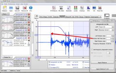
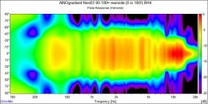
I played a little with old measurements' impulse gate timing and type. 90¤ measurement picks automatically the reflected sound as reference, because it is stronger. In REW we can move Reference timing, but I have only 4ms before the reflection hits. Using a softer slope like Blackman-Harris instead of Tukey however gives more range.
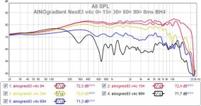
Below I show gating settings for 90¤. I used automatic gating BH4 slope for other angles. This way room effect is minimized. New graphics are more relevant in low F.
When we see measurements eg. these polar spectrograms we usually don't know parameters/setting that were used, there is no standard. Default settings are not the best for every purpose! And defaults are different for every program.
Attachments
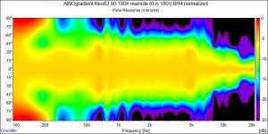
Rearside measurements of AINOgradient were done at smaller number of angles the last time, so this is not as accurate. Normalized looks a bit strange because hottest spl is way off-axis at low F.
Measured response is not symmetrical to frontside, because of measurement conditions. The speaker projects sound now to different direction and thus room reflections are not similar. In real life radiation is fully symmetrical above cardioid effect, except for some frame diffractions that are worse on the frontside. These are mirrored presentations, only one side turn was measured!
Measured response is not symmetrical to frontside, because of measurement conditions. The speaker projects sound now to different direction and thus room reflections are not similar. In real life radiation is fully symmetrical above cardioid effect, except for some frame diffractions that are worse on the frontside. These are mirrored presentations, only one side turn was measured!
Attachments
Last edited:
It is a problem with dipole nulling that cancels sound at near 90¤ angle. The direct sound arrives naturally first, but is weaker that the reflected wavefronts arriving later. Any 1ch measurement system like REW will automatically pick the highest amplitude-impulse for measurement. They are programmed that way and it works for 99% of measurements!
I get that problem with angles 75-105¤. I haven't corrected that im my provious directivity measurements and presentations. It is a detail, it doesn't harm the big picture. Not-corrected it only makes directivity look less dipolic than it really is!
I get that problem with angles 75-105¤. I haven't corrected that im my provious directivity measurements and presentations. It is a detail, it doesn't harm the big picture. Not-corrected it only makes directivity look less dipolic than it really is!
Last edited:
REW has two channel capabilities using soundcard with ASIO drivers.
I see you use OmniMic software for polar response plots. How does this software locate correct impulse peak? I assume you are using USB OmniMic?
With REW in single channel mode, it is better to move desired peak to t=0, otherwise phase is messed up. This happens regardless of how Window Ref Time is set up in IR Windows display.
How are you making measurements for time alignment of drivers?
These were measured with REW and UMIK-1. Response was IR-gated and smoothed in REW. Those responses were exported as txt files and then loaded to Omnimic V2. No processing in Ominimic, just polar graphics. I don't know any details of Omnimic.
I use a DAC for signal, and UMIK has it's own ADC, so 2ch measurement is not possible for me. If I used a speaker design/simulation program, 2ch measurement would make life easier. But I'm not in that level of diy!
I check time alignment by playing the whole (active minidsp-controlled) system (sine sweep) Then I reverse phase of every other driver. Then I look at frequency responses and step responses. During development stage I check phase match by playing only two drivers at same sweep. With dsp it is easy to change delay and measure again, and again , and again etc. Many times I have had phase rolled over one cycle, easy at highest xo!
- Home
- Loudspeakers
- Multi-Way
- Aino gradient - a collaborative speaker project