Ok, after reading a lot, everything is almost set.
After reading that piezo needs different treatment, I went on how to crossover my midbass with a piezo, I decided to follow some suggestions from the POINTED OUT ARTICLE.
When I first went for my crossover values in HERE, I was told to go with the following circuit:
And I was also told (before I realized I had a piezo) that I needed to attenuate my tweeter by 22dB because it seems like the woofer would be 96dB SPL while the tweeter 108dB. So someone told me to calculte an L-Pad in HERE and what I got was:
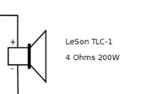
To complicate more, the tweeter box says:
- Always use a 4.7uF/100V polyester capacitor.
Resistor usage table:
Resistor / Sensitivity (2,83 to 1m) / Power Range on 4 Ohms
No Resistor / 108dB / 40W RMS
15 Ohms / 105dB / 60W RMS
18 Ohms / 100dB / 75W RMS
22 Ohms / 97dB / 100W RMS
The label in tweeter box suggests the mentioned capacitor in series with a resistor.
The big question is... alright, I've made an effort... is there any failing thought in the first circuit?
My goal is to level the piezo with the midbass and crossover at 6000Hz/12dB.
After reading that piezo needs different treatment, I went on how to crossover my midbass with a piezo, I decided to follow some suggestions from the POINTED OUT ARTICLE.
An externally hosted image should be here but it was not working when we last tested it.
When I first went for my crossover values in HERE, I was told to go with the following circuit:
An externally hosted image should be here but it was not working when we last tested it.
And I was also told (before I realized I had a piezo) that I needed to attenuate my tweeter by 22dB because it seems like the woofer would be 96dB SPL while the tweeter 108dB. So someone told me to calculte an L-Pad in HERE and what I got was:
An externally hosted image should be here but it was not working when we last tested it.
To complicate more, the tweeter box says:
- Always use a 4.7uF/100V polyester capacitor.
Resistor usage table:
Resistor / Sensitivity (2,83 to 1m) / Power Range on 4 Ohms
No Resistor / 108dB / 40W RMS
15 Ohms / 105dB / 60W RMS
18 Ohms / 100dB / 75W RMS
22 Ohms / 97dB / 100W RMS
The label in tweeter box suggests the mentioned capacitor in series with a resistor.
The big question is... alright, I've made an effort... is there any failing thought in the first circuit?
My goal is to level the piezo with the midbass and crossover at 6000Hz/12dB.
Last edited:
thinking about it , it makes more sense to make R1 variable, take the tap to C2 from the wiper, & it will do attenuation (replace with fixed resistors after you've found the best setting)
The purpose of R1 is to make the Piezo look like a conventional tweeter to the crossover (C1). A Piezo is electrically a capacitor, hence the need for the different treatment
The purpose of R1 is to make the Piezo look like a conventional tweeter to the crossover (C1). A Piezo is electrically a capacitor, hence the need for the different treatment
thinking about it , it makes more sense to make R1 variable, take the tap to C2 from the wiper, & it will do attenuation (replace with fixed resistors after you've found the best setting)
Can you rephase this. What do you mean make R1 variable, did you mean using something like a potentiometer? I'm not familiar with expressions take the tap to C2 from the wiper. What does that exactly mean?
re:"did you mean using something like a potentiometer?" - yes. The wiper is the variable part of the pot, connect C2 to that.
Potentiometers (Beginners' Guide to Pots)
Potentiometers (Beginners' Guide to Pots)
Would it be something like this:
If so, what would be the value for P1.
Also, are the other components subject to change?
Isn't it enough to make an adjustment with the pot and leave like that?
Do I need to find the "right" attenuation by listening?
An externally hosted image should be here but it was not working when we last tested it.
If so, what would be the value for P1.
Also, are the other components subject to change?
Isn't it enough to make an adjustment with the pot and leave like that?
Do I need to find the "right" attenuation by listening?
Hi nickparsons101,
Yes, I finished today ONE module. Well, I did not use the potentiometer. I used the circuit with fixed resistors in their respective values.
The treble was completely suffocated. I shortwired the C1 and P1 junction directly to the tweeter positive (+) and it gave the best result. (Kind of not too bright, but acceptable). I may replace C2 and R2 with a 4,7uF capacitor just for protection in there. I wonder why the necessity of R2 in the end of this story...
Looks like R1 is the real deal on this story. So my preference is in between 15 Ohms and 30 Ohms for R1. I still want to give a shot on these values to see if the sound is better. L1 is working nicely, the sound is very different on another box that is bare.
I must confess I am almost throwing my towel: building and testing this it's very time consuming.
It took me months to find some motivation to keep going on and on.
I have considered acquiring this set...
Genius
Last edited:
Without a resistor in series, the amp sees the piezo as a capacitor, it naturally crosses over around 2000 Hz or so.I wonder why the necessity of R2 in the end of this story...
I must confess I am almost throwing my towel: building and testing this it's very time consuming.
With a capacitor in series with a resistor and the piezo, the resistor allows the piezo to be crossed over at a higher frequency where they don't sound as bad, and also are not as sensitive, the reason you don't need anywhere near as much padding as you thought.
Getting passive crossovers to sound good even with measurement is difficult, and piezos are among the hardest drivers to design crossovers for, they are nothing like a resistive load.
Without a resistor in series, the amp sees the piezo as a capacitor, it naturally crosses over around 2000 Hz or so.
Ok, so what do you suggest... I can't place that 39 Ohm in there, it kills the treble completely, which value should I use. I think the treble attenuation is properly done with R1?
You have not mentioned what type of piezo tweeters you are using, there have been a vast amount of different types produced over the many decades they have been available, all with differing parameters, each would require a different filter to achieve similar response.Ok, so what do you suggest... I can't place that 39 Ohm in there, it kills the treble completely, which value should I use. I think the treble attenuation is properly done with R1?
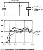
Assuming an original CTS/Motorola "bullet" type, one of the types of crossover below may work OK for what you are trying to accomplish, minimal reduction of HF with more reduction of <3500 Hz. The capacitor value could be reduced for a higher crossover point, and a coil could be added in parallel with the resistor for a steeper, higher crossover.
Can't help you with any more specifics, I never liked the sound of any piezos I have heard (regardless of crossover used), so never have not done any experimentation with them. They vary so widely from unit to unit that any recommendation would be only ballpark anyway.
Attachments

Until tested, there is no way to tell if it can be "adjusted better". And with unit to unit frequency response variation of as much as 10 dB, what works for one might not be close for another.I made modifications to my circuit... what do you think? Can it be adjusted better?
I ask opinion if this is theoretically "OK", if there is no stupid or dumb modifications from the first circuit. Notice that I removed R2 (39 Ohms) entirely.
As for experimentation to see if it's good, like I said before, I shortwired and it sound pretty decent for bare input. In the computer I could equalize a bit the output. I have no further motivation to overtest this anymore, I realize this is a hobby for the passionate. I reached a level of frustration that left with no strengths. The more I mess with it, the more I realize I have to start all over again with different drivers and total new circuit - or get myself proper JBL studio monitors.
To me, the piezo is looking very much like the frugal article, which could or is considered alright to be crossed over this way. But since you are telling you can really never know, well, not in most cases, then what is the point. The specs you are asking are similar to the graph you posted? The manufacturer is a joke: Site under maintenance. I am going to call them right now to see if they have something.
Last edited:
A piezo is not going to be anything like a four ohm load unless it has a built in resistor, so your circuit has at least one flaw. Theoretically, drivers are supposed to be similar, and your crossover might work OK, but look at the response of some real (cheap) piezos:I ask opinion if this is theoretically "OK", if there is no stupid or dumb modifications from the first circuit. The specs you are asking are similar to the graph you posted?
http://www.diyaudio.com/forums/multi-way/253696-graph-ten-goldwood-1005-piezos.html
They vary as much as 20 dB from each other in the 5 kHz region. 10 dB sounds twice or half as loud, 20 dB is a difference of four times. Without measuring your drivers there is no way to know how far they are off from each other, or how similar to any graph you have seen, or whether a circuit may be even remotely appropriate for them.
unless it has a built in resistor, so your circuit has at least one flaw.
Which flaw is that? A -series- resistor missing?
I thought I was following the frugal recomendation....
Piezos are not four ohms.Which flaw is that? A -series- resistor missing?
I thought I was following the frugal recomendation....
Follow whatever your ears tell you.
Attachments
- Status
- This old topic is closed. If you want to reopen this topic, contact a moderator using the "Report Post" button.
- Home
- Loudspeakers
- Multi-Way
- Please check out my final circuit X/O with piezo