Thanks Steve, I should have read the docco in the link I posted earlier a bit more carefully. the splview program is to be used to "normalize" the various frd files. Once you do that the phase data is much more consistent  I'll upload some new ones later on, maybe this evening. That was the bit that was bugging me.
Tony.
I'll upload some new ones later on, maybe this evening. That was the bit that was bugging me. Tony.
Hi Steven, it hasn't been updated for years, but is still available for download at the audua site Speaker Workshop It is also on sourceforge now Speaker Workshop | Free Audio & Video software downloads at SourceForge.net , I'm hoping someone with an interest will pick it up and start developing it again.
The crossover simulation in speaker workshop is very powerful and quite accurate (with a few caveats) I did checks of simulation versus actual final implementation and the results were very close (especially considering the final measurement was done at a different distance, in a different location on a different stand to the measurements used for designing the crossover). http://www.diyaudio.com/forums/multi-way/68301-my-morel-mtm-project-7.html#post2776367
Steve, I've attached new frd files. These ones are MUCH better with respect to the phase. I'm pretty confident that these ones should be ok.
I used the splview program from Jeff's site and normalised the data from 20Hz to 30,000Hz with 2048 points for each driver. I had to cheat a bit with the SB23 and I put in the 20Hz level manually, and also two points at 15Khz and 20Khz 9db lower each than the 10Khz measurement. Without doing that it just never made it to 30Khz and the phase went crazy. It's not really that relevant past about 2K anyway.
Give those a try and also put in the offsets in PCD and see what you get. I haven't tried them yet.
Tony.
Attachments
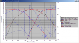
OK I had a play in sw with the new measurements. Attached is what I have at the moment. Still going with the original 300Hz/3000Hz crossover points, but note no driver offsets used, just the basic frd's. This is with 2nd order bessel on the 300Hz and 4th order L/R on the 3000Hz...
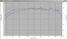
The black curve is the result of the sim. The blue curve is what you get if you put that into Frequency response modeller and apply 44% baffle step (3.1db loss) with an 11" wide baffle. note that I suspect that if I do the actual baffle diffraction sim that it will have a bit of a hump around the 1Khz area where there is currently a dip, which may work to our advantage.
Tony.
Attachments
Hi Steve, I've done a bit more playing. I've now also put baffle step data into each drivers frd's using response modeller, and put everything back into pcd including offsets.
The vertical and horizontal offsets make a little difference but not much, SW models came accross well. Z offset data is a different matter. it has a small but not bad effect for the lower crossover point, enough to be ignored, however it has a much bigger effect for the High pass cross between mid and tweeter. enough to need to consider it. SW does allow Z offset to be used so I can play around with it.
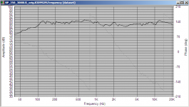
I changed the low frequency crossover point to 350Hz after comparing the non-baffle step corrected and baffle-step corrected plots. Cursor in the screen shot is around 350Hz. Blue trace is uncorrected, black is corrected.
Both non baffle step corrected and baffle step corrected files in the attachment.
note that with the new data the zobel on the tweeter may not be necessary saving a big coil if not. edit, scrub that it didn't look like it was making much difference in PCD but when I took it out in SW the difference was more obvious due to the bigger graph.
Tony.
The vertical and horizontal offsets make a little difference but not much, SW models came accross well. Z offset data is a different matter. it has a small but not bad effect for the lower crossover point, enough to be ignored, however it has a much bigger effect for the High pass cross between mid and tweeter. enough to need to consider it. SW does allow Z offset to be used so I can play around with it.
I changed the low frequency crossover point to 350Hz after comparing the non-baffle step corrected and baffle-step corrected plots. Cursor in the screen shot is around 350Hz. Blue trace is uncorrected, black is corrected.
Both non baffle step corrected and baffle step corrected files in the attachment.
note that with the new data the zobel on the tweeter may not be necessary saving a big coil if not. edit, scrub that it didn't look like it was making much difference in PCD but when I took it out in SW the difference was more obvious due to the bigger graph.
Tony.
Attachments
Last edited:
hi Steve, I wouldnt worry about it. You will probably find it is artifect of the factory measurements. They do them usually in a standard box which is not optimal for the driver. You are better off using modeled response under 200 hz. Try the baffle step adjusted frds you should notice a difference
By the way, is your plan for sealed or vented?
Tony.
By the way, is your plan for sealed or vented?
Tony.
Stevenn,
Just remember that if a mechanical device has a mechanical resonance there is no way to electrically remove that resonance. It does not require and electrical impulse to excite that frequency and no amount of notch filtering will stop that mechanical resonance. It is just the physics of the devices we are working with. That is why we always try to keep the resonant area of a device out of band for how we are using a device, but even then all you are doing is lowering the level of excitation, but it is just lower down in db out of band, it is always there.
Just remember that if a mechanical device has a mechanical resonance there is no way to electrically remove that resonance. It does not require and electrical impulse to excite that frequency and no amount of notch filtering will stop that mechanical resonance. It is just the physics of the devices we are working with. That is why we always try to keep the resonant area of a device out of band for how we are using a device, but even then all you are doing is lowering the level of excitation, but it is just lower down in db out of band, it is always there.
Hi KH, do you think that the anomaly showing in the response attached is a mechanical resonance?
I'd interpreted it as a rising response typical of being in too small a box, but I guess if anything it would be more likely to be in too large a box for manufacturers measurements.
There is a tiny glitch in the impedance curve around the same place as the dip in the middle of the hump, but nothing particularly obvious.
On another note, putting in the z offset (relative to the tweeter) for the mid certainly makes it a lot harder to get decent phase matching! Looking at the cad drawing for the drivers (mid and tweeter) I estimated the offset to be around 18mm (a bit more than Steve's 14mm) This is an area I'm a little uncertain of, as my measurements took care of this (and I had pretty much time aligned drivers as well which makes it easier!)
Steve, are the tweeters flush mounted? how about the mids?? did you get 14mm because the mids are not flush?
Tony.
Attachments
Tony,
What would be really telling here would be a waterfall plot of the speakers decay over time. That is when you start to see a real resonance problem or even a termination problem with a surround or even a glue joint using the wrong adhesive. The impedance curves only show something at one place in time but not the mechanical decay times. That is why waterfall plots are so important when doing a network design at the level of accuracy you are attempting to approach. Resonant behavior of a cone or dome is something that is often overlooked or not well understood by most who are using simulation to do this development. That is part and parcel to why I said it is so important to measure real values in a real box.
Steven
Have to agree on the measuring real values in real box, this is the first time I've seriously tried to simulate from published data. My simulations with real measurements were very successful. There are a number of variables here I don't fully know which makes it tricky. I think that the low frequency crossover seems pretty tolerant, but the tweeter is less so.
I may be trying to go too far, Others have reported this method working well, and I'm sure it should result in something much better than an off the shelf crossover which is what Steve was initially thinking of getting.
I can't seem to get better than 45deg separation on the phase for mid to tweeter with the 18mm offset. perhaps I should just live with that
Tony.
Tony,
45 degrees mismatch is worlds better than most will ever achieve and most people would probably never have the hearing to tell what is happening. The time shift of 45 degree is not much. Remember that most people still listen to speakers with nothing but a single capacitor and one inductor in most commercial speaker systems.
45 degrees mismatch is worlds better than most will ever achieve and most people would probably never have the hearing to tell what is happening. The time shift of 45 degree is not much. Remember that most people still listen to speakers with nothing but a single capacitor and one inductor in most commercial speaker systems.
Me being my usual obsessive self I accidentally discovered if I use a 2nd order bessel on the mid lp and 4th order LR on the tweeter, both at 3Khz I get almost perfect phase tracking and pretty good FR as well. looks better than the symetrical 4th order LR at 3Khz.
Time for me to hang up my hat for a while though, I should post the schematics of what I have done so Steve can play with it some more
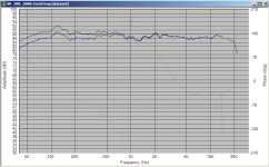
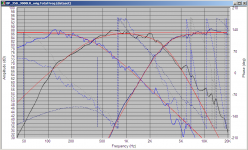
First pic is what I had got too with 2nd order bessel at 350Hz and 4th order LR at 3Khz. Second pic is the summed response.
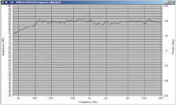
Third pic is with 2nd order bessel at 350Hz and also on the mid at 3000hz with the 4th order LR at 3000Hz from the first pic on the tweeter. Fourth pic is the resulting FR.
Offsets used on the drivers were -18mm for the mid and -40mm for the SB23.
Tony.
I accidentally discovered if I use a 2nd order bessel on the mid lp and 4th order LR on the tweeter, both at 3Khz I get almost perfect phase tracking and pretty good FR as well. looks better than the symetrical 4th order LR at 3Khz. Time for me to hang up my hat for a while though, I should post the schematics of what I have done so Steve can play with it some more
First pic is what I had got too with 2nd order bessel at 350Hz and 4th order LR at 3Khz. Second pic is the summed response.
Third pic is with 2nd order bessel at 350Hz and also on the mid at 3000hz with the 4th order LR at 3000Hz from the first pic on the tweeter. Fourth pic is the resulting FR.
Offsets used on the drivers were -18mm for the mid and -40mm for the SB23.
Tony.
Attachments
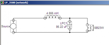
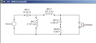
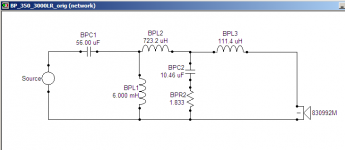
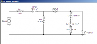
and here are the schematics. Knock yourself out Steve (for real world you will want to adjust to nearest standard values and see how it looks, if ok then you don't need to worry about coming up with strange values).
Third one is the one that has bessel 2nd order slope for both the high and low pass of the bandpass rather than 2nd order on the high pass and 4th order on the low pass.
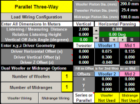
z offsets to put into PCD are -18 and -40 for what I have simmed here the baffle position offsets didn't seem to make much difference but it doesn't hurt to put them in. I don't know if the Z offsets are correct however, they are my best guesses based on the cad diagrams of the drivers as to where the voice coils would be. edit: actually I haven't checked the impedance of these you have to put all of the networks into one in SW to get it to do the impedance, but you can only run the optimizer if you have a single driver (which is why I have separate networks for each driver) the optimizer in SW is great!!
Tony.
edit2: added pcd offsets screenshot.
edit3: added pcd saved file. tweaking the coil in the high pass to 140uH gives a better result I'm stopping now, I promise
(for real world you will want to adjust to nearest standard values and see how it looks, if ok then you don't need to worry about coming up with strange values). Third one is the one that has bessel 2nd order slope for both the high and low pass of the bandpass rather than 2nd order on the high pass and 4th order on the low pass.
z offsets to put into PCD are -18 and -40 for what I have simmed here the baffle position offsets didn't seem to make much difference but it doesn't hurt to put them in. I don't know if the Z offsets are correct however, they are my best guesses based on the cad diagrams of the drivers as to where the voice coils would be. edit: actually I haven't checked the impedance of these
you have to put all of the networks into one in SW to get it to do the impedance, but you can only run the optimizer if you have a single driver (which is why I have separate networks for each driver) the optimizer in SW is great!! Tony.
edit2: added pcd offsets screenshot.
edit3: added pcd saved file. tweaking the coil in the high pass to 140uH gives a better result
I'm stopping now, I promise Attachments
Last edited:
HI Tony
First of all, a big thank you for all yr work. Very much appreciated and way beyond anything I was expecting!
Interestingly, when I compared my own C, Z and L values with yours, they were very close on most components (but way off on a couple).
When I put your values into PCD with csp file, i get graph below (assuming I have components in right place on PCD circuit).
My last attempt at PCD is second graph which appears to have a flatter summed response.
Woofer LP = second order filter
Mid HP = second order
Mid LP = second order
Tweeter = second order parallel
Is this difference between the two the difference between SW and PCD?
So which is best to use?
Cheers
Attachments
Tony,
When you used the Bessel filter section that didn't cause you any in band ripple in the response? That is what I understand from that filter topology. that it causes in band ripple around the crossover point. Just asking a hypothetical here,
Steven
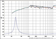
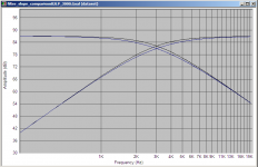
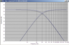
Hi Steven, You aren't thinking of a chebychev filter are you? Bessel does have a bit of a hump at crossover (similar to butterworth but not as much) which can be useful if you have a hole in your response.... The usual complaint about bessel is that the rolloff starts earlier (so you have a wider area of summation, but for 2nd order the rolloff actually starts later than for a LR. 4th order the bessel rollof starts earlier and is deeper. I used 4th order bessel on my MTM's and I'm very happy with it.
The main advantage of bessel is that it has perfectly flat group delay in the pass band, and has the best phase response out of LR, Butterworth and Chebychev filters.
Attached are two comparisons of bessel and LR slopes. Black is bessel and blue is LR. I find it interesting that the 4th order bessel still will sum with a hump compared to the LR, it seems that it would be the opposite when you look at the slopes (the second order seems intuitive that it will have a hump) unless I'm remembering incorrectly and 2nd order has a 1.5db hump and 4th order has a 1.5db dip, that would seem more intuitive......
Tony.
Attachments
Last edited:
- Status
- This old topic is closed. If you want to reopen this topic, contact a moderator using the "Report Post" button.
- Home
- Loudspeakers
- Multi-Way
- WIN ISD Pro and multiway design