Found this definition on Parts Express FAQ:
What is the Difference Between Acoustic and Electric Crossover Slopes?
An electric crossover slope refers to the cutoff produced purely by the electrical components in the crossover. Electrical slopes do not take into account the behavior of the drivers themselves. The combination of both the natural characteristics of the drivers and the electrical filtering produces the acoustic slope. It is in fact this acoustic slope that should be designed around and optimized when building a complete system.
Therefore the option to select different electrical frequencies in Bagby PCD seems to be another variable that can changed to influence values of components and shape of filter curve and is NOT related at all to XO design frequencies.
I think we need a Bagby PCD thread for all Qsn Bagby....
Stevenn,
I would partially disagree with the statement of only looking at the acoustical function. What you have to remember besides the slope and crossover point that is not address by only the acoustical function is the electrical phase angle and interaction of the two signals to each device. You really need to read a book like the Doug Self book on electronic crossovers and all the perturbations of crossovers and the interactions of each type. Though the title says active electronic crossover it does directly apply to and is spoken of in the passive implementations also. You would really do yourself a favor reading something that is more accurate than some of what you are reading, it will help you to truly understand all the factors that many here seem to overlook and often not understand. The slope rate is not the most important factor to look at, that is a simple concept to grasp, but it is only a single piece of the overall design. The summation at the crossover point is more important than the slope chosen. The slope can be as high as 100db per octave with a dsp device or as slow as 6db per octave with a first order crossover. Second and third order crossovers have phase relationship problems at the crossover point and that is why many jump to 4th order as that problem of phase alignment are similar to first order without having the overlap of devices in the pass band.
I would partially disagree with the statement of only looking at the acoustical function. What you have to remember besides the slope and crossover point that is not address by only the acoustical function is the electrical phase angle and interaction of the two signals to each device. You really need to read a book like the Doug Self book on electronic crossovers and all the perturbations of crossovers and the interactions of each type. Though the title says active electronic crossover it does directly apply to and is spoken of in the passive implementations also. You would really do yourself a favor reading something that is more accurate than some of what you are reading, it will help you to truly understand all the factors that many here seem to overlook and often not understand. The slope rate is not the most important factor to look at, that is a simple concept to grasp, but it is only a single piece of the overall design. The summation at the crossover point is more important than the slope chosen. The slope can be as high as 100db per octave with a dsp device or as slow as 6db per octave with a first order crossover. Second and third order crossovers have phase relationship problems at the crossover point and that is why many jump to 4th order as that problem of phase alignment are similar to first order without having the overlap of devices in the pass band.
Hi Kindhornman, I'm not sure how electrical phase is relevant (except from the point of view that to get the desired accoustic phase the electrical phase will have to be some particular value), surely it is the accoustic phase that is relevant, as it is the sound waves themselves that are adding or subtracting depending on whether they are in phase or not.
If accoustic measurements are used in the simulation (or phase is derived from a traced SPL using a hilbert transform) and attention is paid to that phase (see the example I posted earier) then the summation at the crossover should be fine. (and noted depending on the order of the crossover there will be differences in the phase tracking).
Depending on the order of the crossover the phase shift will be different. with 90deg per order being the norm. Perhaps the example I gave earlier is only relevant to 4th order. Certainly the original 2nd order crossover I had had no where near as good a phase tracking, but then I didn't spend the time optimizing it like I did the 4th order.
So maybe it is a semantics issue. Yes the the electrical order is important, in that you need to get it right to hit your correct acoustic target, but if the acoustic target is what you concentrate on, then the electrical side should sort itself out
Tony.
Wintermute,
You may not have realized that by using the 4th order LR filter function you took care of the phase problem fairly well at the crossover point as you would with a first order filter. But if you used a 2nd or 3rd order electrical filter you can not get there in the acoustical response, that is my point exactly. The phase shift of 180 degrees with a 2nd order requires inverting one of the devices and then you still have the time shift at crossover and the 3rd order will give you 270 degrees of shift and that is impossible to correct with any method. Yes the slope is greater so the overlap is much less and so the apparent problem appears less, but you can't fix that acoustically. The 4th order filter is 360 degrees out of phase and you know where that gets you, it is no longer a real problem. Then we have to look at all pass filters and everything else such a Bessel filters and all the rest. It is much more complicated than just looking at part of the problem, that is what I am alluding to here. I wish it was as simple as some want to make it out to be, but it just isn't the case in reality if you dig deep enough.
You may not have realized that by using the 4th order LR filter function you took care of the phase problem fairly well at the crossover point as you would with a first order filter. But if you used a 2nd or 3rd order electrical filter you can not get there in the acoustical response, that is my point exactly. The phase shift of 180 degrees with a 2nd order requires inverting one of the devices and then you still have the time shift at crossover and the 3rd order will give you 270 degrees of shift and that is impossible to correct with any method. Yes the slope is greater so the overlap is much less and so the apparent problem appears less, but you can't fix that acoustically. The 4th order filter is 360 degrees out of phase and you know where that gets you, it is no longer a real problem. Then we have to look at all pass filters and everything else such a Bessel filters and all the rest. It is much more complicated than just looking at part of the problem, that is what I am alluding to here. I wish it was as simple as some want to make it out to be, but it just isn't the case in reality if you dig deep enough.
From the man himself:
"The target transfer function is completely separate and independent from the crossover circuit. The purpose of the target is simply to provide a line on the graph you can "target" as you dial in the crossover values. It may only take a second order electrical filter to achieve a 4th order target when the driver's response is included. They do not have to be the same order.
The crossover frequency that is entered is only used if you have the program calculate textbook values, otherwise it is not used at all. By the way, textbook values are not usually very useful.
Jeff
Hi Steve, yes that sums it up nicely. textbook crossovers assume a resistor for impedance (whereas a driver varies) and ruler flat frequency response. 
KindHornman, I have to admit I struggled getting good phase tracking with my second order version of the crossover. I put it down to the problems I was dealing with with the midbass' response curve, but it could well be otherwise. I had a bit of a play today to try and make it better but didn't get very far.
Tony.
Gents
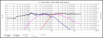
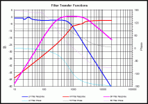
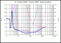
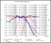
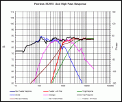
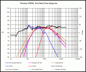
Attached are graphs of my working of PCD crossover. XO 300Hz and 3000Hz
Woofer has Zobel and parallel contour filter.
Tweeter has Zobel, parallel resistor and series RLC
Mid has Zobel and parallel resistor.
I had great difficulty getting a smoooth flat response, the drivers I have are not that compatible, unfortunately.
I am a bit concerned as cost of components and drivers is getting up there with price of good pair of proven speakers, and that is before I have butchered everything with a soldering iron.
All comments welcome...
Attachments
Last edited:
Wintermute,
Try this and I think that you will be happy in the end and will achieve the results that you are after. Remove the crossover from you bass mid. Check the impedance curve with the speaker in the box. Build yourself a conjugate network, an LCR network that goes across the terminals of the speaker as close as you can get. What you are trying to do is make an inverse relationship to the impedance reactance curve of the driver. The resistor value will be a total of the resistance of the capacitor and the inductor and whatever you have to add to be the total. None of the components need to be very large as you are only trying to match the properties of the voicecoils impedance values. The coil can be very small gauge wire. First is the capacitor and Inductor values and finally the resistor to match the level of the voicecoil. When you get this right the impedance curve will be flat, you will have a perfectly resistive load on both the crossover and the amplifier when you are done. My friend who is expert at this does it quickly with a set of inductance and capacitor switchable boxes so he can change values very quickly. Your polar response of the device will be something you will not see any other way. He would kick my *** if he knew I was posting this information. Try it, you will get somewhere you will never get with your speakers any other way. You can do this on the tweeter also, just be careful and do the testing at very low power as you will not have a crossover to cut the low frequencies going to the tweeter. When you get them both to have flat impedance curves then do your crossovers, you will be pleasantly surprise in the results. Best polar response you will ever get and the amplifier will function with the lowest distortion levels as the feedback circuit does not have to fight the external pole of the speaker that it has no way of correcting.
Try this and I think that you will be happy in the end and will achieve the results that you are after. Remove the crossover from you bass mid. Check the impedance curve with the speaker in the box. Build yourself a conjugate network, an LCR network that goes across the terminals of the speaker as close as you can get. What you are trying to do is make an inverse relationship to the impedance reactance curve of the driver. The resistor value will be a total of the resistance of the capacitor and the inductor and whatever you have to add to be the total. None of the components need to be very large as you are only trying to match the properties of the voicecoils impedance values. The coil can be very small gauge wire. First is the capacitor and Inductor values and finally the resistor to match the level of the voicecoil. When you get this right the impedance curve will be flat, you will have a perfectly resistive load on both the crossover and the amplifier when you are done. My friend who is expert at this does it quickly with a set of inductance and capacitor switchable boxes so he can change values very quickly. Your polar response of the device will be something you will not see any other way. He would kick my *** if he knew I was posting this information. Try it, you will get somewhere you will never get with your speakers any other way. You can do this on the tweeter also, just be careful and do the testing at very low power as you will not have a crossover to cut the low frequencies going to the tweeter. When you get them both to have flat impedance curves then do your crossovers, you will be pleasantly surprise in the results. Best polar response you will ever get and the amplifier will function with the lowest distortion levels as the feedback circuit does not have to fight the external pole of the speaker that it has no way of correcting.
Thanks yr replies.
Kindhornman - You have not said why this is necessary. There are Zobel ciricuits for all 3 drivers. What is it specifically in graphs I posted that you are concerned about?
Wintermute - I already have mid and tweeters. A Peerless 8" 831868 doesn't have the peak in SPL response like SB 23 but is more than double the cost.
Cheers
Stevenn,
A Zobel is not a conjugate network, It does not have an inverse relationship to the moving coil in a gap. Yes it does flatten the impedance curve but it does not do the same thing as the conjugate network that eliminate both impedance, phase shift and the back emf wave in the same manner. Ignore what I said, it doesn't matter, but I was trying to tell you something that you will not get from the simplicity of the Zobel network.
A Zobel is not a conjugate network, It does not have an inverse relationship to the moving coil in a gap. Yes it does flatten the impedance curve but it does not do the same thing as the conjugate network that eliminate both impedance, phase shift and the back emf wave in the same manner. Ignore what I said, it doesn't matter, but I was trying to tell you something that you will not get from the simplicity of the Zobel network.
Also Stevenn as the XO on the woofer is in an area where the impedance is probably already equal to the DCR there is probably no need for a Zobel network on it. A Zobel on the tweeter would be there to flatten the impedance for the amplifiers sake too, so if cost is becoming an issue that part of the network could be eliminated as well
The most cogent explanation I can find to post here comes from another thread where this is discussed in detail. I think that this covers most of what is going on. It is another pole in the crossover and changes the transfer function of the speaker amplifier circuit. I wish I could explain it as well as my friend did to me and I know that there is more to it than meets the eye. I will just post the explanation that covers the basic of the conjugate network.
That all sounds very nice, but it is not exactly what happens. I've prepared a couple of sims to try and show what is actually going on. First of all, if the electrical damping of the driver changed, then it's impedance would have to change. Back in 2004 this was a topic of discussion on the Madisound board for the case of a series resistor changing the damping. My analysis showed that while the damping of the system (again note the word system, not driver) changes, the damping of the driver doesn't. Qes of the driver never changes. The impedance of the drivers is fixed.
Next, in the figures below, recognize that everything to the right of the capacitor represents some impedance load, ZL, that the capacitance sees. What happens without the LRC (which is a conjugate network) is that this load (the driver alone) has both resistive and reactive components (capacitance and inductance). The series capacitance of the 1st order crossover in combination with the inductive component of the driver's impedance at the impedance peak forms a LC resonance. You can see this in the first figure below where a cap is in series with a model of a driver's Z.
Next to it I have replace the model of the driver's Z with an inductor in series with a resistance. You can see similar behavior.
In the next figure I have added a conjugate network which eliminates the the reactive components in the in the load, ZL, making it purely resistive. As you can see, there is no resonance peak in the response now because there is no inductive component in the load for the capacitor to resonate with.
But the impedance of the driver model remains the same. Yes, the conjugate network has an impedance of 4.4 ohms at impedance peak of the driver model, and yes this does provide a current path to ground, but what suppresses the peak in the response curve is the elimination of the reactive nature of the load seen by the cap. This can be better observed by replacing the conjugate network with a 4.4 ohm resistor, the same value as that in the conjugate network. The last figure shows a comparison between the response with the conjugate network in red and when the shunt is just a 4.4 ohm resistor in blue. The resistor does add the same damping to the system at Fs as the conjugate network and therefore the LC resonance between the crossover cap and the inductive component of the driver's Z has a lower peak. But it is still present because the reactive components in the driver's Z have not be compensated for. (Note that the value of the series cap has been changed to compensate fro the difference impedance so as to keep the crossover point the same.)
So it is not so simple as to say the LRC provides a current path to ground and therefore damps the resonance. There is more to it. Te correct conjugate network eliminates the cause of the resonance be removing the reactive components in the driver's Z around Fs. This is exactly the same as what a Zobel does to eliminate the effect of the rising impedance due to voice coil inductance. In neither case does the driver's impedance change. What changes is the impedance the upstream elements in the crossover network see, and how they interact with that impedance.
That all sounds very nice, but it is not exactly what happens. I've prepared a couple of sims to try and show what is actually going on. First of all, if the electrical damping of the driver changed, then it's impedance would have to change. Back in 2004 this was a topic of discussion on the Madisound board for the case of a series resistor changing the damping. My analysis showed that while the damping of the system (again note the word system, not driver) changes, the damping of the driver doesn't. Qes of the driver never changes. The impedance of the drivers is fixed.
Next, in the figures below, recognize that everything to the right of the capacitor represents some impedance load, ZL, that the capacitance sees. What happens without the LRC (which is a conjugate network) is that this load (the driver alone) has both resistive and reactive components (capacitance and inductance). The series capacitance of the 1st order crossover in combination with the inductive component of the driver's impedance at the impedance peak forms a LC resonance. You can see this in the first figure below where a cap is in series with a model of a driver's Z.
Next to it I have replace the model of the driver's Z with an inductor in series with a resistance. You can see similar behavior.
An externally hosted image should be here but it was not working when we last tested it.
In the next figure I have added a conjugate network which eliminates the the reactive components in the in the load, ZL, making it purely resistive. As you can see, there is no resonance peak in the response now because there is no inductive component in the load for the capacitor to resonate with.
An externally hosted image should be here but it was not working when we last tested it.
But the impedance of the driver model remains the same. Yes, the conjugate network has an impedance of 4.4 ohms at impedance peak of the driver model, and yes this does provide a current path to ground, but what suppresses the peak in the response curve is the elimination of the reactive nature of the load seen by the cap. This can be better observed by replacing the conjugate network with a 4.4 ohm resistor, the same value as that in the conjugate network. The last figure shows a comparison between the response with the conjugate network in red and when the shunt is just a 4.4 ohm resistor in blue. The resistor does add the same damping to the system at Fs as the conjugate network and therefore the LC resonance between the crossover cap and the inductive component of the driver's Z has a lower peak. But it is still present because the reactive components in the driver's Z have not be compensated for. (Note that the value of the series cap has been changed to compensate fro the difference impedance so as to keep the crossover point the same.)
An externally hosted image should be here but it was not working when we last tested it.
So it is not so simple as to say the LRC provides a current path to ground and therefore damps the resonance. There is more to it. Te correct conjugate network eliminates the cause of the resonance be removing the reactive components in the driver's Z around Fs. This is exactly the same as what a Zobel does to eliminate the effect of the rising impedance due to voice coil inductance. In neither case does the driver's impedance change. What changes is the impedance the upstream elements in the crossover network see, and how they interact with that impedance.
Here is another link discussing the LRC conjugate tank circuit. Take a look, you can control the Q of the circuit in a way that you can not do with the Zobel RC circuit alone.
Introduction
Introduction
Kindhornman.
Thank you for your detailed post, which I just about understand.
The conjugate network would seem to be a great tool for use in advanced design and is worthy of a thread all of its own. Surely top brand speakers should incorporate this as a matter of routine?
However I have neither tools or instruments (switchbox?)to measure the parameters suggested, nor the where withall to determine sizes of the particular components involved.
I started this thread with a view to getting members' help as newbie in renovating a pair of speakers by using some freely available recognised software WinIsd and PCD and whilst I feel my understanding of Physics involved has improved, I am no closer to starting this and in particular have no confidence in my results which I have posted for critique.
A quality speaker kit is starting to look like a good option!
- Status
- This old topic is closed. If you want to reopen this topic, contact a moderator using the "Report Post" button.
- Home
- Loudspeakers
- Multi-Way
- WIN ISD Pro and multiway design
