Only as a generalisation There are so many variable
I tend to use the Weems advice ( beginners book and well worth finding a second hand copy )
Great sound stereo speaker manual - David B. Weems, G. R. Koonce - Google Books
I also try and make my midrange work as wide as possible and this is why I like 4 and 5 inch midrange drivers
Also
Designing, Building, and Testing Your Own Speaker System with Projects: David Weems: 9780070694293: Amazon.com: Books
Speaker Building 201: A Comprehensive Course in Speaker Design: Ray Alden: 9781882580453: Amazon.com: Books
Introduction to Loudspeaker Design: John L. Murphy: 9780966377323: Amazon.com: Books
Afternoon all.
Wrestling with JBagby's crossover designer and having some fun understanding it , reckon I am about 80% there...
Two qsns on Bagby v7:
1. If a target transfer function of a particular order is selected, presumably the selected filter order has to be the same?
2. After entering target pass frequencies, Bagby then calls for 'the selected electrical frequency' to be entered in circuit and component section. What is this?
Probably wrong thread to be asking these questions in.....
Thanks
OK Now please take this with a grain of common sense as I am a beginner.
A lot depends on where you place the filter, if the driver has 2 octaves of flat response on either side of the frequency where you put the filter the response shape may be the same as the electrical shape ( 1/2/3 or 4 dB per octave ) but if you put for example a second order electrical filter where a drivers response is starting to roll off the resultant acoustic response sums and the actual acoustic slope may be 3rd or 4th order.
You want both the drivers to be about 6dB down at the XO frequency and the little Peerless will probably be happy to cross at 250/300 Hz with a second order filter in front of it, where-as if you put a second order filter at 200 Hz the acoustic response may then become 4th order as the interaction of the electrical filter and the natural roll-of combine. But keep in mind that asymmetric XOs are normal and common, what is important is the acoustic summation to a relatively flat response.
I would be using the little Peerless mid 300 to 3000Hz myself, second order electrical at both ends and manipulating the XO on the woofer and tweeter to match, although at 3k a first order may work there is the peak at around 8k that would probably be evident
Sounds ok to me moondog, though I myself only have one speaker design under my belt ") I think the important thing to grasp as you have said is that it is the combination of the electrical filter and the driver that makes the final acoustic slope, and it is this final acoustic slope that matters.
I think the important thing to grasp as you have said is that it is the combination of the electrical filter and the driver that makes the final acoustic slope, and it is this final acoustic slope that matters.
So the target is the acoustic target, you vary your electrical until you get that (or close to it).
Tony.
I think the important thing to grasp as you have said is that it is the combination of the electrical filter and the driver that makes the final acoustic slope, and it is this final acoustic slope that matters. So the target is the acoustic target, you vary your electrical until you get that (or close to it).
Tony.
One often overlooked point of a crossover design is the actual impedance measurement of the speakers at the crossover point chosen. Do not just use a number like 8ohms at crossover. You need to understand that isn't the real value that you need to use. The actual impedance of the speaker in the box you are using at the crossover point will give you the impedance value that you need to use for the crossover point. This goes for both the upper and lower crossover points of a band pass filter. So if the mid range driver has a 6.4 ohm value at the lower frequency of the bandpass and say 8.7 ohms at the higher frequency point those are the values that you will need to use in your filter design to actually produce a crossover with the correct electrical filter. If you are using a Zobel or conjugate network on the speaker to flatten the impedance rise on a device then you need to develop this first and again remeasure the speakers impedance curve to plug in the electrical impedance at the crossover points to truly have the frequency points you have chosen and also the electrical -3db or -6db points that will sum correctly! If you do not do this your values will not be correct, the crossover point will not sum correctly. Remember also that you should check your network connected to the speaker after you build the network as the normal quality of a capacitor and many times an inductor can be as wide as 10 to 20% of the real values you have chosen. You will then need to adjust your values to make the crossover function correctly. This is the real reason that people often talk about why when substituting capacitors in a crossover from one brand to another of the same type that they say they hear a difference in their speakers, the actual values of the substituted components are not exactly the same over their value range and this is actually shifting the crossover point and changing the slope. This is the difference between an accurate crossover and one that is chosen based strictly on theoretical values only!
Thanks guys your replies.
The woofer and mid driver impedance charts have large peaks which i plan to attenuate with Zobel circuit.
Still not sure on the PCD qsns, my logic (?!) says that as target response shape is a function of the filter used, it doesn't make sense to try and match a First order Butterworth target response with a Third Order parallel filter, for example.
And what is electrical frequency?
Cheers
Stevenn,
I think what he was trying to convey was that the electrical response can be different than the actual acoustical response curve. They are not one and the same. Though you can put a 2nd or 4th order filter on the speaker you have to add this to the acoustical rolloff of the speaker, they are additive and not necessarily coincident to each other. If the speaker is rolling off naturally this will add to the electrical filters curve. I don't think that the tendency for many to only look at the acoustical slope is important as much as that the two crossover points are coincident at the -3db or -6db point dependent on the slope that you chose. That is why I tried to point out that a simulation only using electrical response of an ideal network does not often do what it is supposed to. The values of the electrical components have to be exacting and the impedance at crossover of the two devices have to be known true values.
I think what he was trying to convey was that the electrical response can be different than the actual acoustical response curve. They are not one and the same. Though you can put a 2nd or 4th order filter on the speaker you have to add this to the acoustical rolloff of the speaker, they are additive and not necessarily coincident to each other. If the speaker is rolling off naturally this will add to the electrical filters curve. I don't think that the tendency for many to only look at the acoustical slope is important as much as that the two crossover points are coincident at the -3db or -6db point dependent on the slope that you chose. That is why I tried to point out that a simulation only using electrical response of an ideal network does not often do what it is supposed to. The values of the electrical components have to be exacting and the impedance at crossover of the two devices have to be known true values.
Yes but the target acoustic shape is often much greater than first order, often the target is a 4th order LR shape or similar.
But if you have a driver with a good second order shape roll-off, lets say a tweeter then a first order electrical ( a single cap in series ) will give you a third order response acoustically and all you need to do is use a frequency where little bass gets through.
Use a second order filter and power handling increases so you can play louder
So much depends on how much power ( how loud do you personally play music?) the driver needs to handle.
For example my bedroom speakers [ 2.5 Way] will only be asked to play to about 90dB at most so I am using a single cap on the tweeter and running the Vifa P-13 full range in a 7 liter sealed box; and the speaker will be handling only about 30 watts peak.
With a proper second order XO at 300 Hertz the little Vifa alone could handle triple that with ease.
Electrical frequency is my shorthand for the calculated filter response using components into a fixed resistance, and you can calculate or get from tables.
Just for your information at around 300 hertz most woofers have an impedance equal or close to their DCR and often [sometimes] a drivers nominal impedance is given as the impedance at the XO frequency.
Zobels are used to flatten the impedance at a higher frequency so a great help when using book crossovers based on nominal impedance.
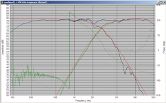
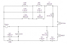
Hi Steve, I've attached an example here from my own crossover.
The target was 4th order bessel at 2.8Khz. The red traces represent that target.
The crossover to actually achieve that target consisted of a couple of notch filters and a second order electrical filter on the woofers, and a third order electrical on the tweeter. This crossover is quite a complex one but I was struggling with a few things that made it hard to get a good match to my target, I got there in the end though
Other things to look at (other than seemingly flat frequency response) are how well the phase of the two speakers tracks through the crossover region (dotted lines on the graph)
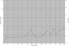
What Kindhornman said about impedance is something to watch for as well. I spent ages coming up with a super flat frequency response in the simulator but had not been simulating the impedance, I decided I should check it only to find that the impedance was dropping to about 1 ohm in places. Luckily I realized before I built it!! So do check the impedance!!
Tony.
The target was 4th order bessel at 2.8Khz. The red traces represent that target.
The crossover to actually achieve that target consisted of a couple of notch filters and a second order electrical filter on the woofers, and a third order electrical on the tweeter. This crossover is quite a complex one but I was struggling with a few things that made it hard to get a good match to my target, I got there in the end though
Other things to look at (other than seemingly flat frequency response) are how well the phase of the two speakers tracks through the crossover region (dotted lines on the graph)
What Kindhornman said about impedance is something to watch for as well. I spent ages coming up with a super flat frequency response in the simulator but had not been simulating the impedance, I decided I should check it only to find that the impedance was dropping to about 1 ohm in places. Luckily I realized before I built it!! So do check the impedance!!
Tony.
Attachments
Thanks yr replies and examples. I think we are all on the same wavelength (pun intended!).
My qsns refer directly to the use of Jeff Bagby's spread sheet and what selections to make.
So I select the target response curve I want but this is a name only and might as well be curve 1,2,3 or 4 and then try and match it with filter order and component value?
Clear as mud?
Comments about impedance noted, Bagby can model this as well and this is next step once I resolve above queries.
Thanks
Yes select your target response curve and then using the various electrical filters try and get the speakers curve to match it. Don't be afraid to set the filter to be different than what you would expect it to be, the end goal is to have the acoustic output of the drivers matching your goal.
Tony.
Tony.
Thanks
i created impedance files in the first place from datasheets using SPL trace as Bagby PCD will not work without them.
Moondog - 'LR 2nd as the design goal' - what does this mean?
Also can anyone answer qsn as to what 'selected electrical frequency' means and does in Bagby PCD?
Thanks
i created impedance files in the first place from datasheets using SPL trace as Bagby PCD will not work without them.
Moondog - 'LR 2nd as the design goal' - what does this mean?
Also can anyone answer qsn as to what 'selected electrical frequency' means and does in Bagby PCD?
Thanks
- Status
- This old topic is closed. If you want to reopen this topic, contact a moderator using the "Report Post" button.
- Home
- Loudspeakers
- Multi-Way
- WIN ISD Pro and multiway design