Thank you everyone for your replies
As much as I want the best possible sound and most accurate reproduction, I have to compromise somewhere. The speakers are in use every day as they are now part of entertainment system so i cannot have too much downtime, I have a busy new job, two children under 4 and other demands on my time like my other half. I just don't think I have the time to make up components that may not work through my own faulty workmanship.
Thank you Tony for offer of loan of crossovers, might take you up on that.
One qsn - why would ready built Daytona units be inferior to a something home made?
Also prices mentioned don't add up to much savings - $25 x2 for circuit boards, $70 for copper wire plus other components will be pretty much cost of Daytons.....
Hi Steve, Have a read through this thread http://www.diyaudio.com/forums/mult...designing-crossovers-without-measurement.html and I think you will start to see why doing something yourself should result in something better than buying an off the shelf crossover.
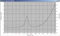
Off the shelf crossovers are usually text book designs that assume they are working into a constant resistance. Speakers do not provide a constant impedance but usually a rising one. See below the attached impedance measurement of my MW144 drivers in their cabinet.
You can see that depending on what the crossover frequency is the resistance is different. a crossover for a particular frequency is dependent on the resistance of the load. so a crossover designed for 4 ohms at 3Khz will be off on my speakers because at 3Khz the impedance has rizen to nearly 6 ohms, additionally it may not attenuate properly due to the constantly rising impedance after that. In my case I simulated to get very close to the desired acoustic response something that a text book design would not have achieved even if I did put in the correct resistance (unless I used a zobel on the drivers which flattens the impedance).
There is also the issue that a text book crossover assumes a completely flat frequency response in the crossover region (and some way either side). In reality the drivers normally have their own rollof and this combines with the electrical rolloff of the crossover to produce the actual acoustic rolloff. This may result in holes or humps in the sound depending on the drivers involved.
Having said all that, I lived with my three ways with off the shelf crossovers, and drivers that didn't match that well for nearly 20 years and was quite happy with them. They still sounded better than most other peoples systems that I heard, It wasn't till I heard something REALLY good that I realized I could do a whole lot better. That was what started me on the quest to make my own from scratch")
Tony.
Off the shelf crossovers are usually text book designs that assume they are working into a constant resistance. Speakers do not provide a constant impedance but usually a rising one. See below the attached impedance measurement of my MW144 drivers in their cabinet.
You can see that depending on what the crossover frequency is the resistance is different. a crossover for a particular frequency is dependent on the resistance of the load. so a crossover designed for 4 ohms at 3Khz will be off on my speakers because at 3Khz the impedance has rizen to nearly 6 ohms, additionally it may not attenuate properly due to the constantly rising impedance after that. In my case I simulated to get very close to the desired acoustic response something that a text book design would not have achieved even if I did put in the correct resistance (unless I used a zobel on the drivers which flattens the impedance).
There is also the issue that a text book crossover assumes a completely flat frequency response in the crossover region (and some way either side). In reality the drivers normally have their own rollof and this combines with the electrical rolloff of the crossover to produce the actual acoustic rolloff. This may result in holes or humps in the sound depending on the drivers involved.
Having said all that, I lived with my three ways with off the shelf crossovers, and drivers that didn't match that well for nearly 20 years and was quite happy with them. They still sounded better than most other peoples systems that I heard, It wasn't till I heard something REALLY good that I realized I could do a whole lot better. That was what started me on the quest to make my own from scratch
Tony.
Attachments
Last edited:
I have seen a very good link to a how to solder tutorial but I didn't book mark it Basically I allways clean the leads of the things I am soldering, usually with a bit of 400grit wet and dry, and then wipe off with a cloth soaked in metho.
I did a bit of a google search and found this tutorial which looks pretty good. http://www.elecraft.com/TechNotes/N0SS_SolderNotes/N0SS_SolderNotesV6.pdf
Regarding the use of winisd. If you are crossing over in the lower part of the drivers response range then yes using the modeled response for your cabinet is probably best as the manufacturers specs tend to be done with standard baffles and volumes which are not necessarily optimal for the driver, but when looking at higher frequency crossover points (towards the top end of the drivers range) then you definitely want to use the manufacturers specs, or even better your own measurements on your own baffle, as the sim will show this as being totally flat, but the manufacturers spl curves will show that the driver is far from completely flat.
Another aspect which wont be taken into consideration with winisd OR manufacturers specs is baffle step. This can be modeled, but if you have real measurements on the baffle this is best. You can calculate what the baffle step frequency will be with a simple formula. A good explanation of baffle step is here --> Baffle Step Compensation note that Rod presents a line level solution, but it can also be done in the crossover. How much you need is room and placement specific!
I can relate to the issue of time that you mentioned earlier. I have a five year old, she was three when I was getting back into the project. It severely limits the amount of time you have for doing stuff!
I've only designed the crossover for my two way MTM, it was definitely a learning experience! A three way is apparently a lot harder to get right. I'm surprised no one has jumped in and said don't do it yet!! Having been there and done that (and not regretted it) I guess I am a little more on the side of saying if you want to learn then why not jump in.
Anyway do some reading and get a feel for what you are up against and then decide whether you want to spend the cash, or perhaps try something a little easier
Tony.
Basically I allways clean the leads of the things I am soldering, usually with a bit of 400grit wet and dry, and then wipe off with a cloth soaked in metho. I did a bit of a google search and found this tutorial which looks pretty good. http://www.elecraft.com/TechNotes/N0SS_SolderNotes/N0SS_SolderNotesV6.pdf
Regarding the use of winisd. If you are crossing over in the lower part of the drivers response range then yes using the modeled response for your cabinet is probably best as the manufacturers specs tend to be done with standard baffles and volumes which are not necessarily optimal for the driver, but when looking at higher frequency crossover points (towards the top end of the drivers range) then you definitely want to use the manufacturers specs, or even better your own measurements on your own baffle, as the sim will show this as being totally flat, but the manufacturers spl curves will show that the driver is far from completely flat.
Another aspect which wont be taken into consideration with winisd OR manufacturers specs is baffle step. This can be modeled, but if you have real measurements on the baffle this is best. You can calculate what the baffle step frequency will be with a simple formula. A good explanation of baffle step is here --> Baffle Step Compensation note that Rod presents a line level solution, but it can also be done in the crossover. How much you need is room and placement specific!
I can relate to the issue of time that you mentioned earlier. I have a five year old, she was three when I was getting back into the project. It severely limits the amount of time you have for doing stuff!
I've only designed the crossover for my two way MTM, it was definitely a learning experience! A three way is apparently a lot harder to get right. I'm surprised no one has jumped in and said don't do it yet!! Having been there and done that (and not regretted it) I guess I am a little more on the side of saying if you want to learn then why not jump in.
Anyway do some reading and get a feel for what you are up against and then decide whether you want to spend the cash, or perhaps try something a little easier
Tony.
Steven what drivers have you decided on??
Best advice I was ever given ( and read too ) was to keep the midrange to the widest possible bandwidth and the "telephone" bandwidth 0f 300Hz to 300Hz was going to be my suggested starting point
Buy the best midrange you can afford is also good advice
Best advice I was ever given ( and read too ) was to keep the midrange to the widest possible bandwidth and the "telephone" bandwidth 0f 300Hz to 300Hz was going to be my suggested starting point
Buy the best midrange you can afford is also good advice
sorry I took the soldering comment at face value, you never know the experience level of new members WES have solen inductors, Speaker Bug linked above by Moondog have jantzen which are very good value for money.
for my prototype I actually got inductors from jaycar (mainly because I could just go and buy them). But they are quite high DCR and I'd go with the janztens next time. The solens are available in larger wire gauges if you need really low DCR.
For caps I can't go past PartsConnexion AXON caps AXON True Cap Metallized Polypropylene Capacitors They are nothing flash, but they are good quality. I bought a range of sizes (since they are so cheap) so that I could experiment. If you keep the weight to below 250g (including packaging) the shipping via post is only around $10.00
Tony.
Ok guys you win! I will have a go at my own crossovers.
I love my music and it is a tantalising prospect to think that there may be more to discover in the music that I know well.
Mids are 4 in Peerless 830992. I am guessing moondog means 300Hz - 300 kHz?
Cheers
I love my music and it is a tantalising prospect to think that there may be more to discover in the music that I know well.
Mids are 4 in Peerless 830992. I am guessing moondog means 300Hz - 300 kHz?
Cheers
Last edited:
Nope 300 to 3000 Tweeter handles everything higher than 3000Hz
Maybe 4000 for a really good small midrange
http://www.tymphany.com/files/HDS-P830992 Rev2_0_0.pdf
Fs of the Peerless is 89Hz so 2 octaves above resonance if 360Hz and if you look at the performance graph it gets very ratty and broken up above 8k
You need to pick a XO point where the drivers response is reasonably flat and smooth for an octave ( at least ) above and below the XO point so in this instance 3k looks OK to me. It is a design starting point anyway
Moon,
From the chart, that does not look like the "very good midrange" that I too am looking for. I would not use that thing above 2.5K with at least third order and them probably need a notch filter. Major breakup at 5K. Might use that with a big 12 inch in a floor stander, but you are still stuck with a crossover in the sensitive hearing range. No XT-25 here. I bet it is pretty sweet in the 200 to 2K range.
From the chart, that does not look like the "very good midrange" that I too am looking for. I would not use that thing above 2.5K with at least third order and them probably need a notch filter. Major breakup at 5K. Might use that with a big 12 inch in a floor stander, but you are still stuck with a crossover in the sensitive hearing range. No XT-25 here. I bet it is pretty sweet in the 200 to 2K range.
Gawd! Just when i thought i was strating to understand this, you guys get all technical on me
From a session reading Allen B tutorial, plus reviewing comments here and data sheets of proposed and actual drivers, I get the following driver operating ranges:
Woofer 8in SB23NRXS45-8 0-300Hz
Mid 4in Peerless 830992 300-2500Hz
Tweeter Peerless 812978 2500+ Hz
Basically I treat my 3 way as 2 x 2 ways and try and bring every thing back to common or lowest driver sensitivity SPL?
Logic dictates that you start with tweeter and work backwards?
Win ISd does not appear to allow modelling of sealed tweeters, I assume you just run with manufacturer's data? But then how do you model impedance?
Cheers
Afternoon all
Having studied AllenB article, another site Diyaudioandvideo plus instructions in the 3 way PCBs, I am feeling a little more confident. However latest qsn is concerning the bandpass filter crossover frequencies. If I am using 300 Hz and 2400 Hz for my low and high pass frequencies respectively, are these the same frequencies used for bandpass filter, I.e.
300Hz is bandpass High Pass and 2400 Hz is bandpass Low Pass?
Also woofer and mid impedances have peaks at their Fs of 27 and 89 Hz respectively so will these require impedance attenuation or are they sufficiently distant from cross over to be dampened sufficiently?
Thanks
89 X 2 = 178 X 2 = 356 so not quite 2 octaves, but slightly greater than 1 1/2 octaves. What is the size of the midrange internal box and what is the midrange "In box" resonance?
If the midrange in box resonance is below 180/200 then it is OK if not perfect and XO spread can be dependent on slope. if using 300 as the bandpass high pass and both crossovers use 2nd order electrical then it may be OK, but if using a first order slope on the woofer then it may need to be crossed a little lower. I read a book by Weems which recommended using the inverse bandpass ratio to set the woofer and tweeter XO points. 2700/300=9 so 1/9 so use 270 for the woofer and 3k for the tweeter General sort of guideline and not gospel but it gives you an idea of the things that need thinking about
If the midrange in box resonance is below 180/200 then it is OK if not perfect and XO spread can be dependent on slope. if using 300 as the bandpass high pass and both crossovers use 2nd order electrical then it may be OK, but if using a first order slope on the woofer then it may need to be crossed a little lower. I read a book by Weems which recommended using the inverse bandpass ratio to set the woofer and tweeter XO points. 2700/300=9 so 1/9 so use 270 for the woofer and 3k for the tweeter General sort of guideline and not gospel but it gives you an idea of the things that need thinking about
I just put some figures into the box program. the Peerless will work in any volume from 1 litre to 10 litres but the optimum for power handling Vs musicality seems to be between 4 and 7 litres
At 4 litres the Fc is 112 Hz using the bigger box (7l) it is 103Hz and you could get away with a first order ( a single cap in series ) at 300 but the midrange clarity would probably be better with the second order
At 4 litres the Fc is 112 Hz using the bigger box (7l) it is 103Hz and you could get away with a first order ( a single cap in series ) at 300 but the midrange clarity would probably be better with the second order
Thanks Moondog
There seem to be quite a few little tricks the more I read of this topic.
Mid sealed box resonance 113Hz (Unibox) and 109Hz (winIsd) with vol 4.5 litres.
Reason for qsn re bandpass freq is that PCBs instructions contain tables for high/low crossover frequency components plus bandpass frequencies with first and second order crossovers.
So am I correct in assuming values to be used in table for bandpass crossovers are the same ones as for high and low crossovers in general?
Cheers
Last edited:
- Status
- This old topic is closed. If you want to reopen this topic, contact a moderator using the "Report Post" button.
- Home
- Loudspeakers
- Multi-Way
- WIN ISD Pro and multiway design