Hey folks, I am building a two way with Peerless 830875 woofers and Vifa PL27TG35-06 tweeters.
I'm close to having the cabinet's finished and I've been looking around at similar projects to get an idea for the crossover (basically trying to find something really close and do some tweaks).
I found a project at this URL:
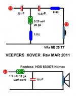
Veeper TM Monitor
They are really close, very close volume of cabinet, almost the same FB, same woofers and tweeters that are very close.
My question is can anyone give me a pointer on what to adjust on the tweeter crossover for my slightly different tweeter? The basic differences are:
My tweeter is 0.5db less efficient (insignificant?)
Impedance of my tweeter is 6 ohms Vs 3.6 ohms for the veepers
Everything else is pretty darn close, even the frequency response. I'll attach the veeper crossover diagram for your reference. I'm thinking of copying the woofer crossover part exactly, I'm guessing I just need a resistor change on the tweeter portion to deal with the slightly different impendance of my tweeters (2 ohms more).
Am I correct in just needing a resistor tweak? If so which should I change, thanks!!
Chris
I'm close to having the cabinet's finished and I've been looking around at similar projects to get an idea for the crossover (basically trying to find something really close and do some tweaks).
I found a project at this URL:
Veeper TM Monitor
They are really close, very close volume of cabinet, almost the same FB, same woofers and tweeters that are very close.
My question is can anyone give me a pointer on what to adjust on the tweeter crossover for my slightly different tweeter? The basic differences are:
My tweeter is 0.5db less efficient (insignificant?)
Impedance of my tweeter is 6 ohms Vs 3.6 ohms for the veepers
Everything else is pretty darn close, even the frequency response. I'll attach the veeper crossover diagram for your reference. I'm thinking of copying the woofer crossover part exactly, I'm guessing I just need a resistor change on the tweeter portion to deal with the slightly different impendance of my tweeters (2 ohms more).
Am I correct in just needing a resistor tweak? If so which should I change, thanks!!
Chris
Attachments
Last edited:


Question I have to ask:
Is your objective to have a good, proven, speaker? If so, buy the Vifa tweeter, make the Veeper and live happily ever after.
Or
Do you want to learn about designing a crossover? Is so, don't copy Lou's Veeper, but check out this forum, and design your own. http://www.diyaudio.com/forums/mult...designing-crossovers-without-measurement.html
Thanks guys, I think I should learn more about crossover design myself but I appreciate your help. Dissi I will study this and try it out in my model, I'm trying "the passive crossover design 7.0" in excel.
So far I've managed to put together a 2nd order from parts from my old speakers and they work very well although they are not optimal. I'll experiment some more before ordering the proper components!
So far I've managed to put together a 2nd order from parts from my old speakers and they work very well although they are not optimal. I'll experiment some more before ordering the proper components!
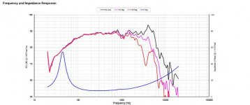
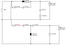
Quite an interesting bass driver, the Peerless 830875. It has some breakup rubbish around 4-6kHz that our Troels found merited a notch:
PEERLESS-NOMEX-164
He uses a "Tank" at 6.1kHz here across the bass coil to drop the troublesome cone breakup about 6dB. I fancied that 10uF was a bit steep with Veepers 1.5mH. Changed to 6.8uF and 1.5R, much the same as Troels did. The tweeter crossover looks fairly generic with 6 ohm 90dB tweeters and phase matching is nice. An 87dB tweeter would probably get away with second order and lose the 10uF, and have a smaller 3 ohms at the filter input to match levels.
For those who can't do this notch stuff in their head: Alan Yates' Laboratory - VK2ZAY's Engineering Calculators - LCR Resonance
The value of a tank capacitor varies with the bass coil, but I see no point in making it too deep. I've ended up with a 6.1kHz notch just like Troels. He knows what he's doing.")
PEERLESS-NOMEX-164
He uses a "Tank" at 6.1kHz here across the bass coil to drop the troublesome cone breakup about 6dB. I fancied that 10uF was a bit steep with Veepers 1.5mH. Changed to 6.8uF and 1.5R, much the same as Troels did. The tweeter crossover looks fairly generic with 6 ohm 90dB tweeters and phase matching is nice. An 87dB tweeter would probably get away with second order and lose the 10uF, and have a smaller 3 ohms at the filter input to match levels.
For those who can't do this notch stuff in their head: Alan Yates' Laboratory - VK2ZAY's Engineering Calculators - LCR Resonance
The value of a tank capacitor varies with the bass coil, but I see no point in making it too deep. I've ended up with a 6.1kHz notch just like Troels. He knows what he's doing.
Attachments
Here's some sims PCD
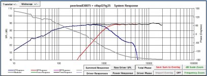
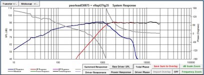
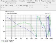
So I'm trying to understand phase on the tweeter on a 2nd order filter, from what I understand the tweeter should be flipped because on the first plot below the phase is 180 degrees from the woofer at the crossover point?
Flipping the phase means having to adjust the crossover and gives a phase profile that gradually slopes, this is more ideal?
Attachments
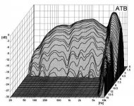
bart-dood, I get used to going over people's heads at this forum, and taking a lot of flak in the process. But if you want to get the best out of that Peerless 830875, it is important to equalise out the peak at 4-6kHz.
These peaks represent energy storage, best exemplified by the waterfall plot of aluminium Visaton AL170S driver below. The Nomex (paper) driver has similar issues, though not as dramatic.
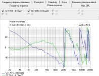
The two phase plots are for the circuit I posted for the Peerless 830875 circuit. The first is with the essential tank, the second without it. I could do this another sort of notch, but you get the idea I hope. It's the difference between an average speaker and a very good one. We are, after all, PROFESSIONALS.
These peaks represent energy storage, best exemplified by the waterfall plot of aluminium Visaton AL170S driver below. The Nomex (paper) driver has similar issues, though not as dramatic.
The two phase plots are for the circuit I posted for the Peerless 830875 circuit. The first is with the essential tank, the second without it. I could do this another sort of notch, but you get the idea I hope. It's the difference between an average speaker and a very good one. We are, after all, PROFESSIONALS.
Attachments
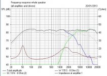
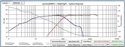
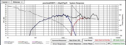
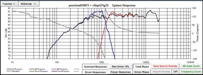
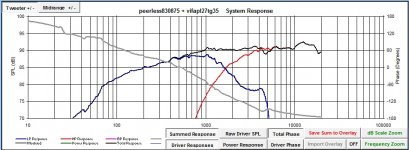
Think I'm getting the hang of this a bit more now, Dissi I modelled up your Xover in PCD7.0 and then my crossover. Here's the comparison, yours is about 86db and mine about 90db.
It's very interesting to compare my simulation with the results of PCD. I see not much difference above 400 Hz, great. But the question is: what is below 400 Hz? Assuming a vented box tuned to 54 Hz, my simulation predicts a woofer sensitivity of 86 dB. For that reason my design is matched to 86 dB.
To answer your question regarding phase matching of woofer and tweeter: Proper phase matching is achieved, when the sum at the crossover frequency is 6 dB higher than the individual spl of woofer and tweeter. Reversing the tweeter polarity then gives a deep notch of -20 dB or more.
Concerning crossover frequency: Google yourself, but some people do not recommend to use that tweeter below 2 kHz.
Hi Chris,
Concerning the woofer, The Elsinore and the Nomex 164 are crossing the 830875 at ~3 Khz.
Concerning the level of the woofer, take a look at the section concerning BSC at the link below.
http://www.diyaudio.com/forums/mult...designing-crossovers-without-measurement.html
Concerning crossover frequency: Google yourself, but some people do not recommend to use that tweeter below 2 kHz.
Concerning the woofer, The Elsinore and the Nomex 164 are crossing the 830875 at ~3 Khz.
Concerning the level of the woofer, take a look at the section concerning BSC at the link below.
http://www.diyaudio.com/forums/mult...designing-crossovers-without-measurement.html
It's very interesting to compare my simulation with the results of PCD. I see not much difference above 400 Hz, great. But the question is: what is below 400 Hz? Assuming a vented box tuned to 54 Hz, my simulation predicts a woofer sensitivity of 86 dB. For that reason my design is matched to 86 dB.
To answer your question regarding phase matching of woofer and tweeter: Proper phase matching is achieved, when the sum at the crossover frequency is 6 dB higher than the individual spl of woofer and tweeter. Reversing the tweeter polarity then gives a deep notch of -20 dB or more.
Concerning crossover frequency: Google yourself, but some people do not recommend to use that tweeter below 2 kHz.
I guess I'm more confused now regarding the sum at the crossover, shouldn't PCD sim show me what the expected response is? The plots I'm getting out of it show a relatively flat sum between the tweeter and woofer but the individual values aren't 6db below the sum. Does this mean the responses from PCD should not be taken as accurate? If it were it should show a peaking at the crossover point?
I didn't sim the vent and box with PCD, I used winISD to figure out the port tuning and box volume, hence why it is missing from my plots.
- Status
- This old topic is closed. If you want to reopen this topic, contact a moderator using the "Report Post" button.
- Home
- Loudspeakers
- Multi-Way
- Help with Veeper tweeker