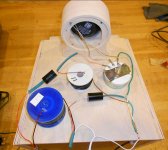
This started on the Full Range page; TB W5 8ohm driver. Guitar and Bass strings sound great but lacking high end, especially with coat of silicon.
Trying to lean a bit about xo's - very intriguing. I've always known enough to call Madisound, if I wanted something that worked properly.
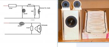
Lots of on-line ox calculator sites, Second order Butterworth looks straightforward. I can see why some say to use same impedance drivers (tweeter on right is 8ohm, so is woofer).
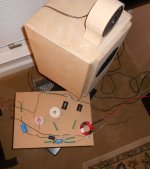
I did have enough parts to listen to them; xo as shown.
Where do I go from here?
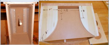
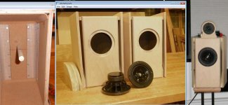
Some box construction plans here:
http://www.diyaudio.com/forums/full-range/219785-w5-1611-saf-sequel.html
Trying to lean a bit about xo's - very intriguing. I've always known enough to call Madisound, if I wanted something that worked properly.
Lots of on-line ox calculator sites, Second order Butterworth looks straightforward. I can see why some say to use same impedance drivers (tweeter on right is 8ohm, so is woofer).
I did have enough parts to listen to them; xo as shown.
Where do I go from here?
Some box construction plans here:
http://www.diyaudio.com/forums/full-range/219785-w5-1611-saf-sequel.html
Attachments
Ok where to start. The first thing to learn is that text book xo will almost never be right. Measure the impedance of the drivers in the cabinet! Second it is the acoustic slope that matters not the electrical.
Check out the excellent sticky. Designing without measurements for a good grounding!
Tony.
Check out the excellent sticky. Designing without measurements for a good grounding!
Tony.
I might be able to get a buddy to help measure the impedance (tomorrow)
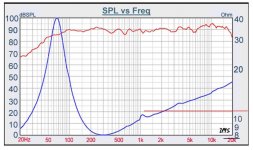
So far some songs are sounding very nice. However the woofer is not rolling off at 2200hz, still going to 3500hz or so. (I didn't think the woofer would roll off easily)
The tweeter roll off is close, however to loud.
L-Pad (now) R1= 1.0 ohm R2= 50ohm
So far some songs are sounding very nice. However the woofer is not rolling off at 2200hz, still going to 3500hz or so. (I didn't think the woofer would roll off easily)
The tweeter roll off is close, however to loud.
L-Pad (now) R1= 1.0 ohm R2= 50ohm
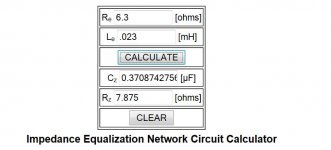
Based on the spec sheet http://www.parts-express.com/pdf/264-898s.pdf , it looks like the woofers have an impedance of around 10 ohms at 2200 and have risen to around 14 ohms by 20Khz.... did you do your calculations based on 8 ohms nominal impedance?
Some impedance compensation will probably help (if you don't have acoustic measurements and simulation capabilities).
Also it looks like the woofers FR starts rising at around 1Khz and is about 5db hotter at 10Khz. factor in baffle step as well and you could be around 9db higher (on the TB) from about 3Khz up than you are from 100 - 1000 Hz!
Tony.
Sorry - should have posted this - this one is:
http://www.parts-express.com/pedocs/specs/264-918-tang-band-w5-1611saf-specifications.pdf
http://www.parts-express.com/pedocs/specs/264-918-tang-band-w5-1611saf-specifications.pdf
ok that doesn't have the same rising response, but the impedance is even higher than 10ohms at 2200 ") It's a bit hard to see on that graph exactly what it is though, since it seems to be a log scale on the impedance, and the lines don't match up with discreet impedance values. If you can get an actual impedance measurement that would be best.
It's a bit hard to see on that graph exactly what it is though, since it seems to be a log scale on the impedance, and the lines don't match up with discreet impedance values. If you can get an actual impedance measurement that would be best.
Tony.
It's a bit hard to see on that graph exactly what it is though, since it seems to be a log scale on the impedance, and the lines don't match up with discreet impedance values. If you can get an actual impedance measurement that would be best. Tony.
 to that!
Where do I go from here?
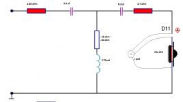
The baffle step causes a rising frequency response in the midrange and demands a larger coil to compensate. According to a simulation 1.5 mH and 12 uF could work. The target function is a 3rd order Butterworth low-pass filter having -6 dB at 2.2 kHz:

Dissi thanks!
I was busy this morning and made up new 1.1 coils. HUGE improvement in middle - however still needs work.
Btw, the tweeter L-pad is just cracked open 1/16 of a turn and tweeters are just wailing away
The bass is crazy nice!!!! they have potential if the xo can be resolved and/or buy different tweeters. [they are old but working/clear]
* the volume is not turned up much on pre-amp either, just a bump i.e. plenty loud.
Attachments
Last edited:
I'm not sure where that plot came from - that's what the bass curve looks like - exactly!
The box is tuned to 51-52hz.
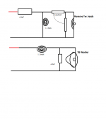
I went and looked at a 3rd order Butterworth circuit, typical it has two coils, so a little confused there.
I had a pair or clarity caps 3.9 (vs. 4.7uF), so slipped them for the tweeter(s) - a whole sweeter!
The box is tuned to 51-52hz.
I went and looked at a 3rd order Butterworth circuit, typical it has two coils, so a little confused there.
I had a pair or clarity caps 3.9 (vs. 4.7uF), so slipped them for the tweeter(s) - a whole sweeter!
I added wire to the 1.1mh coils, now 1.5mf and added the 12uf cap.
Much better - the woofers were overbearing, now much quieter.
I'll find somebody to measure the response - I'll get there someday also
added construction pic.
Much better - the woofers were overbearing, now much quieter.
I'll find somebody to measure the response - I'll get there someday also
added construction pic.
The baffle step causes a rising frequency response in the midrange and demands a larger coil to compensate. According to a simulation 1.5 mH and 12 uF could work. The target function is a 3rd order Butterworth low-pass filter having -6 dB at 2.2 kHz:
View attachment 321894
Attachments
Last edited:
I'll take you up on that offer.
Was just checking around for new tweeters - these are interesting:
89db - 8ohm - good price.
Morel MDT 12 1-1/8" Neodymium Tweeter 277-060
Was just checking around for new tweeters - these are interesting:
89db - 8ohm - good price.
Morel MDT 12 1-1/8" Neodymium Tweeter 277-060
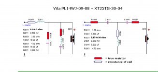
DIY fellow sent this link - this xo may be direction to head.
The midbass(s) are similar and I have the tweeters.
Vifa PL14WJ-
The midbass(s) are similar and I have the tweeters.
Vifa PL14WJ-
Maybe time to LEAP into action:
Crossover Design: The Madisound Speaker Store
Yes persistence - these boxes have HUGE, bigger than life sound!
Crossover Design: The Madisound Speaker Store
Yes persistence - these boxes have HUGE, bigger than life sound!
Attachments
Last edited:
That is an option, but maybe you should wait till you can do some acoustic measurements of your own and see what you can come up with. You are on the right track, so if you keep it up I'm sure you will at the very least learn something, and hopefully come up with something that you are very happy with as well!
Tony.
Tony.
- Status
- This old topic is closed. If you want to reopen this topic, contact a moderator using the "Report Post" button.
- Home
- Loudspeakers
- Multi-Way
- Canned Crossover Design - What Next?