There's a neat way to measure coils - but forgot 
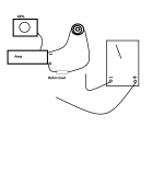
See diag. by sweeping the generator and measuring in two places the volts will/can be the same.
Once the freq. is found, divide by number (again forgot) by the freq.
I usually test with a 1.0mH to get me going (and can compair to factory coils)
Can somebody refresh my memory plz? - I'll mark the dial on the Gen next time - .5 .6 .7. 8. 9. etc.... and/or make a chart.
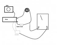
Attachments
Last edited:
I believe you are talking about f1 and f2 which are 0.7071 times the peak voltage which represents the resonant Z of the coil. However isnt it simples just to find the voltage at the peak instead?
Either way, you need to measure current too.
EDIT: your question befuddled me. Im quoting Qts measurement. Oops. I just measure V and I at a single given F. Divide V by Xl to calculate Z, if you take V and I then you have Z. Rearrange to get Xl. Then sub F and Xl into inductive reactance equation.
Either way, you need to measure current too.
EDIT: your question befuddled me. Im quoting Qts measurement. Oops. I just measure V and I at a single given F. Divide V by Xl to calculate Z, if you take V and I then you have Z. Rearrange to get Xl. Then sub F and Xl into inductive reactance equation.
Last edited:
XL = 2*pi*f*L and Z = V/I and XL = Z.
take a point at F, measuring V and I. Calculate Z.
Sub XL and F into 1st formula and rearrange to find L.
Thats correct i think (bearing in mind im writing this on the bus home from work after a xmas holiday of ONE day )
)
however it occurs to me that you may mean the pulsed voltage method, which i rarely use.
take a point at F, measuring V and I. Calculate Z.
Sub XL and F into 1st formula and rearrange to find L.
Thats correct i think (bearing in mind im writing this on the bus home from work after a xmas holiday of ONE day
)however it occurs to me that you may mean the pulsed voltage method, which i rarely use.
Last edited:
I use speaker workshop and use the passive measurement option. It seems pretty accurate. The other thing I have done is to parallel with a close tolerance cap and do an impedance sweep, and then work out the value of the coil based on the resonant frequency of the LC combo (knowing the value of the cap).
Tony.
Tony.

When the voltage is the same across the resistor and the inductor, the inductive reactance is equal to the resistor value. Don't compare either one against the whole output of the amp, it won't be twice the other two measurements! (Extra credit if you can say why and what the amp's output voltage is relative to the voltage across the resistor or inductor).
For an 8 ohm resistor, you get:
8 = 2 * pi * f * l
l = 8 / (2 * pi * f)
l = 0.785 / f
For an 8 ohm resistor, you get:
8 = 2 * pi * f * l
l = 8 / (2 * pi * f)
l = 0.785 / f


When the voltage is the same across the resistor and the inductor, the inductive reactance is equal to the resistor value. Don't compare either one against the whole output of the amp, it won't be twice the other two measurements! (Extra credit if you can say why and what the amp's output voltage is relative to the voltage across the resistor or inductor).
When reactance of the coil equals resistance of the resistor or R, total impedance equals 1.414 times R. Then the equal voltage drops across the resistor and coil, by voltage division, that is R or Xl divided by the total impedance times the applied voltage of the amp or Ei, equals 0.707 times Ei. So Ei equals 1.414 times the voltage across resistor or inductor.
I like these kinds of quizzes.
The neat thing about this method, I believe, is that the voltmeter can be a "regular" one, that is, it can have a relatively narrow range of accurately measuring AC Voltage, usually not greater than 1 kHz, and the method still works.
Regards,
Pete
That is not correct.When reactance of the coil equals resistance of the resistor or R, total impedance equals 1.414 times R.
And the voltage value isn't relevant to the measurement.
What I learned, other than (and with less precision than) a Maxwell or Hay bridge,
a 60Hz AC signal can be applied to a variable resistance and the inductor DUT in series. When XL = R the inductance L is found by
L = R/376.8
where R is the final setting of the variable resistance.
Or, using any useful audio frequency with the same connection as above, but with a 1-ohm resistor in place of the variable one, measure the voltage across the resistor and the inductor. The inductance L is then found by
L = Rv / 2*pi*F*Lv
where Rv is the voltage across the resistor, F is the frequency of the AC signal, and Lv is the voltage across the inductor.
My extra credit is... can someone calculate the denominator in the formula for the first setup when using a 50Hz signal?
edit: and yeah denominator isn't the right word, but it's late and that's what came to mind easily. More easily than divisor.
Last edited:
That is not correct.
And the voltage value isn't relevant to the measurement.
Unless you are like Kirchhoff risen from the dead, you can't expect us to accept your judgement based on authority. If what I say is the total impedance is incorrect, than what is the correct value, and how did you arrive at it?
Zt = [(Xl)^2 + R^2]^1/2
Substitute Xl = R, and go from there. This is basic textbook electronics.
Regards,
Pete
i agree. It is basic AC theory. Im still a basic person.
I see it as this:
Z = R+jX
So id just measure Z at a convenient frequency measuring mV across a shunt, say 10 Ohm, volts from the joint of coil and amp to ground. Measure DCR. Textbook stuff. Set volts, measure mV across shunt to get mA.
Accurate enough i think.
I use it for rotor impedance tests at work regularly
My DMM was cheap, £20. It measures to 400hz to a fraction of a percent. Thats plenty high enough, unless youre making 0.001 uH coils...
Last edited:
- Status
- This old topic is closed. If you want to reopen this topic, contact a moderator using the "Report Post" button.
- Home
- Loudspeakers
- Multi-Way
- Help - Forgot how to measure coils