Thank you, inductor!
Yeah, I know, my english 'vocabulary' is not adequate, I'm sorry")
I Have to search a lot of words to translate them in Dutch to understand what is meant That doesn't make it easy
Wayne was also helpfull and mentioned that the de250 + H290C needs a 8dB attenuation with my active X-over.
But that I can't just use the components + values of the compensation part of the 4pi crossover: the compensation part is not an individual part, it interacts with the splitter filter. It's more complicated then I thought.
New challenge: finding a filter that simply compensates the de250 (without the complete crossover).
Dumptruck talked about CD compensation on more sofisticated active crossovers. It doesn't sound THAT bad.
However, it's more challenging to make a passive compensation filter that I can put between my amp and de250.
Yeah, I know, my english 'vocabulary' is not adequate, I'm sorry
I Have to search a lot of words to translate them in Dutch to understand what is meant
That doesn't make it easy Wayne was also helpfull and mentioned that the de250 + H290C needs a 8dB attenuation with my active X-over.
But that I can't just use the components + values of the compensation part of the 4pi crossover: the compensation part is not an individual part, it interacts with the splitter filter. It's more complicated then I thought.
New challenge: finding a filter that simply compensates the de250 (without the complete crossover).
Dumptruck talked about CD compensation on more sofisticated active crossovers. It doesn't sound THAT bad.
However, it's more challenging to make a passive compensation filter that I can put between my amp and de250.
I know. What you said (besides the vocabulary being difficult for you) you already know. (And) That's why a lot of people don't understand, I can assure you. You go to basics with Wayne and that's why. Very down to earth...the compensation part is not an individual part, it interacts with the splitter filter. It's more complicated then I thought.
You have the high impedance (and compensation) that's going to give you the lift of the high frequency but you add the L-pad (hybrid with compensation) to bring the output down at pass band. It interacts with the 3. order crossover.
If the "de250 + H290C needs a 8dB attenuation" active, do you make the rest 4dB L-pad in a passive configuration? With compensation/cap or without? Does it need to be modeled in SPICE or is it straight forward?
I read a lot on his forum and I understand the basics of crossovers (the top octave compensation, matching the sensitivities of the tweeter and the horn, the highpass and lowpassfilter and avoiding 'nulls').
This link + video, that Wayne sent me, helped me a lot:
AudioRoundTable.com: Measurement => Crossover optimization for DI-matched two-way speakers
However, there is a difference between understanding the basics and making crossovers on your own
I just don't have the time to read read read and try with all sorts of components to get a configuration that sums the drivers perfectly through the crossover region and to make a configuration that compensates the CD on his own.
Would it sound 'disastrous' if I just connect the drivers with the amps (both in phase of course), filtered at 1.6khz with the active crossover, compensating the CD manually by matching the sensitivity of the tweeter before mass-rolloff with the sensitivity of the woofer and compensate the higher frequencies with the treble knob on my preamp?
Last edited:
Clever, that's probably why you have 4dB headroom...... and compensate the higher frequencies with the treble knob on my preamp?
(8+4=12)
I don't think Wayne wants his crossovers posted publicly, guys, but is anyone else confused about the resistors? 25Ω in series with the DE250 doesn't work... I must be reading it wrong?
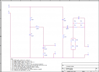
Anyway, you can use 2.2uF and 10Ω (resistor and capacitor connected in parallel with each other, and then in series with the DE250). It's not very elegant, because of the impedance (compare the brown filter curve with my hybrid one posted earlier), but it will work. You can put 16Ω across the DE250 terminals to damp it a little better at 2kHz... that might be just fine after the active LR4 is applied.
Anyway, you can use 2.2uF and 10Ω (resistor and capacitor connected in parallel with each other, and then in series with the DE250). It's not very elegant, because of the impedance (compare the brown filter curve with my hybrid one posted earlier), but it will work. You can put 16Ω across the DE250 terminals to damp it a little better at 2kHz... that might be just fine after the active LR4 is applied.
Attachments
Last edited:
Not at all! The link I posted refers to his forum. However, he explains a lot in his forum, if you want to, you can find everything there.I don't think Wayne wants his crossovers posted publicly
Does the configuration that you propose (2.2uF and 10 ohm resistor + 16 ohm parallel with the de250) give me the compensation (about 8db atenuation) that is needed for the compression driver on a CD horn?
It's that I don't know how to transfer the theory in values and components
I understand the goals of crossovers and compensation circuits, but I can't make them myself.For a good result, do I need to do other things then CD compensation using an active crossover?
Last edited:
I have no idea of what you are talking about. In relation to Wayne's work in the passive crossover attenuation it's evident that 12dB attenuation comes from a 25/16 L-pad like it was posted before by vandevoordekoen on post #58.I don't think Wayne wants his crossovers posted publicly, guys, but is anyone else confused about the resistors? 25Ω in series with the DE250 doesn't work... I must be reading it wrong?
vandevoordekoen,
From previous posts I would not regard dumptruck comments as very enlightening, and I would take them with a grain of salt. That's all I have to say. Please follow Wayne's P. suggestions if you want to achieve a successful speaker project. He has all the keys because he has been there.
From previous posts I would not regard dumptruck comments as very enlightening, and I would take them with a grain of salt. That's all I have to say. Please follow Wayne's P. suggestions if you want to achieve a successful speaker project. He has all the keys because he has been there.
For goodness sake, I was simply saying I was having a problem simulating the pi4 high pass, using Wayne's measurements. I didn't mean to imply Wayne made a mistake in his crossover. I've been designing, simulating, building, and measuring exactly this type of crossover for the past year, and I mostly learned from Wayne's writing on CD speakers. If I have made a mistake about something in this thread, please explain what it is.vandevoordekoen,
From previous posts I would not regard dumptruck comments as very enlightening, and I would take them with a grain of salt. That's all I have to say. Please follow Wayne's P. suggestions if you want to achieve a successful speaker project. He has all the keys because he has been there.
I don't suppose you are at all interested, but here is the problem I'm getting in simulating the pi4 crossover as it was posted.
Attachments
Last edited:
Maybe this is a better way to put my question on the 4 pi crossover:
If the pad is 25/16, the impedance of the driver around 10Ω, then in parallel with 16Ω it's about 6Ω, then add 25Ω in series, you get ~30Ω. This is why the simulation doesn't work, but more importantly, it's not the HF impedance of the 4 pi (Pi Speakers - four Pi loudspeaker performance data), so what am I not getting here? EDIT: oh, backwards pad, I got it now.
If the pad is 25/16, the impedance of the driver around 10Ω, then in parallel with 16Ω it's about 6Ω, then add 25Ω in series, you get ~30Ω. This is why the simulation doesn't work, but more importantly, it's not the HF impedance of the 4 pi (Pi Speakers - four Pi loudspeaker performance data), so what am I not getting here? EDIT: oh, backwards pad, I got it now.
Last edited:
I guess Inductor will give you a better answer then I could do
All I know is that Wayne told me that the 4pi crossover is one system (the compensation part interacting with the rest of the crossover). Maybe there are other parts of the crossover that you omitted in the simulation but that are important to make it work?
All I know is that Wayne told me that the 4pi crossover is one system (the compensation part interacting with the rest of the crossover). Maybe there are other parts of the crossover that you omitted in the simulation but that are important to make it work?
I figured it out, got it to match his system measurement. It is true that Wayne's crossover can't be split up, which is why we are talking about these stand-alone CD compensation circuits in the first place. If Wayne wants to design one, that would obviously be great for your purposes, and please post it here.
If Wayne wants to design one, that would obviously be great for your purposes, and please post it here.
I kwow, but I can't ask that from Wayne. He already gives so much important information that is the result of decades of work, the 'secret' of his perfect speakers. It would be asking too much.
But making a circuit that compensates the DE250 and that summs perfectly the drivers through the crossover region is unfortunately not for me. I have neither the advanced knowledge nor the time to do so
Because I'm a little bit tight on budget, I'll use the 'oldschool-crossover' for a while: picking a crossover frequency and slope for each driver with the active crossover (too bad I can't delay the drivers with the crossover because it's not too sofisticated). I guess this will also sound good (but not perfect).
When I have more budget, and when I know exactly how the modified 4pi speakers sound like, I will do the update to one of Waynes (perfect) passive crossovers. Then I will also hear the difference of a perfect crossover, which will satisfy me even more
All I read on the forum and on Waynes forum has been very helpfull to understand the goal of crossovers and the beauty of a perfect crossover that matches the different drivers!
When I start building the cabinets, some photos will be posted to illustrate the goal of this thread
The phase alignment/tracking is the real meat of the crossover design. I don't know where time alignment is starting out in a 4 pi without crossover, but if you get lucky you'll can get phase to line up at least a little bit at some acceptable active crossover point (1300-1600 acoustic or so).
As far as the compensation circuit I gave you, I assure you it's a trivial bit of passive EQ that you can use with confidence and even tweak by ear. It's nothing as fussy as an actual passive crossover. It would be nice if somebody would pop in to back me up on that since apparently I'm suspected of being clueless, but I guess you could post what I gave you in another thread or forum for a second opinion.
As far as the compensation circuit I gave you, I assure you it's a trivial bit of passive EQ that you can use with confidence and even tweak by ear. It's nothing as fussy as an actual passive crossover. It would be nice if somebody would pop in to back me up on that since apparently I'm suspected of being clueless, but I guess you could post what I gave you in another thread or forum for a second opinion.
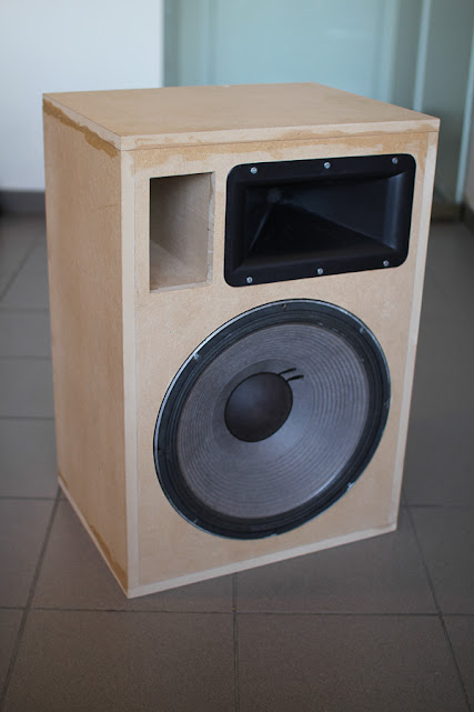
Hello, it has been a while, but I found some time and started building the 4pi speakers, in a temporary active crossover version.
Later, when I'll have put some money aside (once again) for the 4pi project, I'll upgrade them with diy passive crossovers, following the schematics of Waynes design.
I bought the B&C de250 drivers in Belgium, Wayne shipped 2 H290C horns (they sound great! even without CD compensation), and I could buy 2 second hand JBL 2226 drivers.
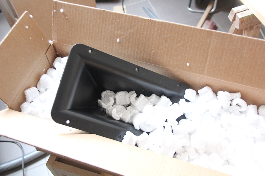
horns arrived!
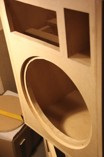
Bought 2 MDF panels (240cm * 122cm, 1 speaker = 1 panel) and started with the bass reflex ports:


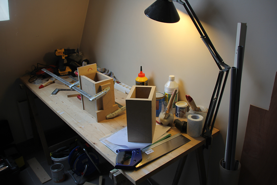
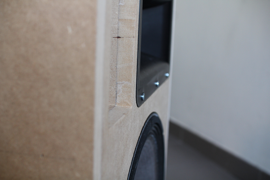
strengthened the opening for the JBL driver
glued the bassport to the front baffle
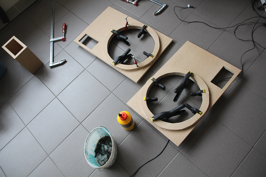
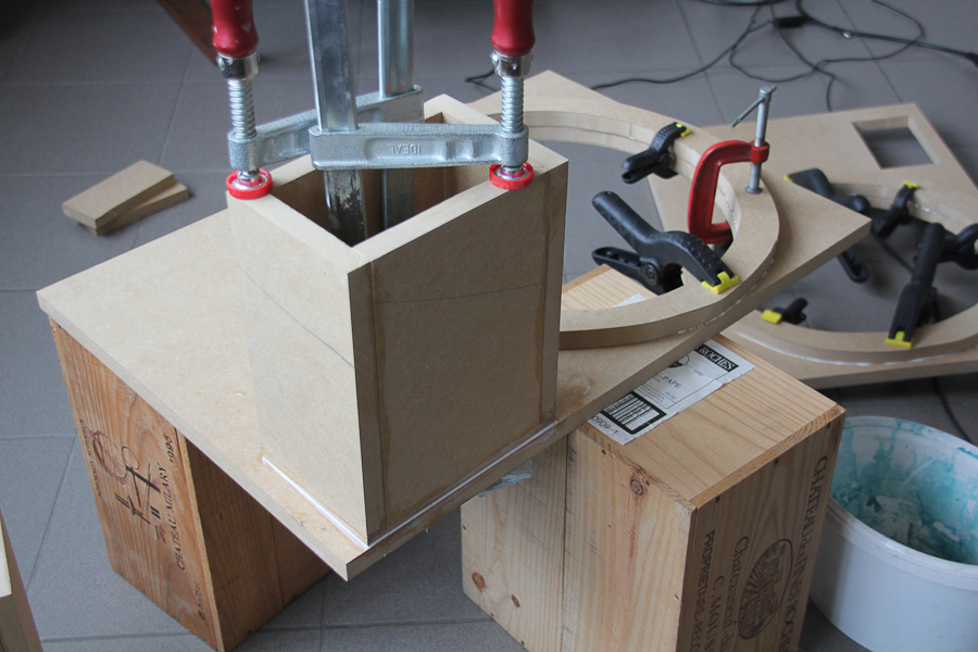
the cabinets are rising!

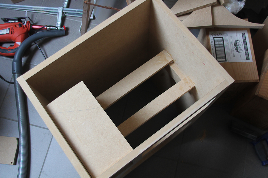
Installing braces between woofer and tweeter (for isolation material)

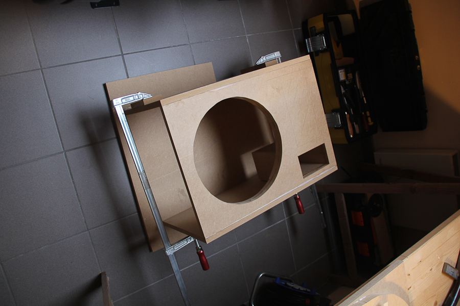
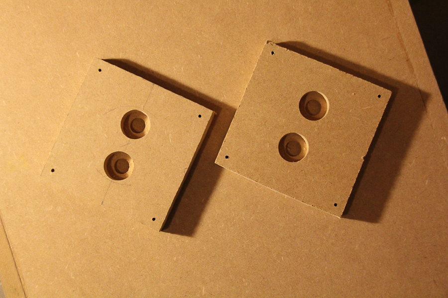
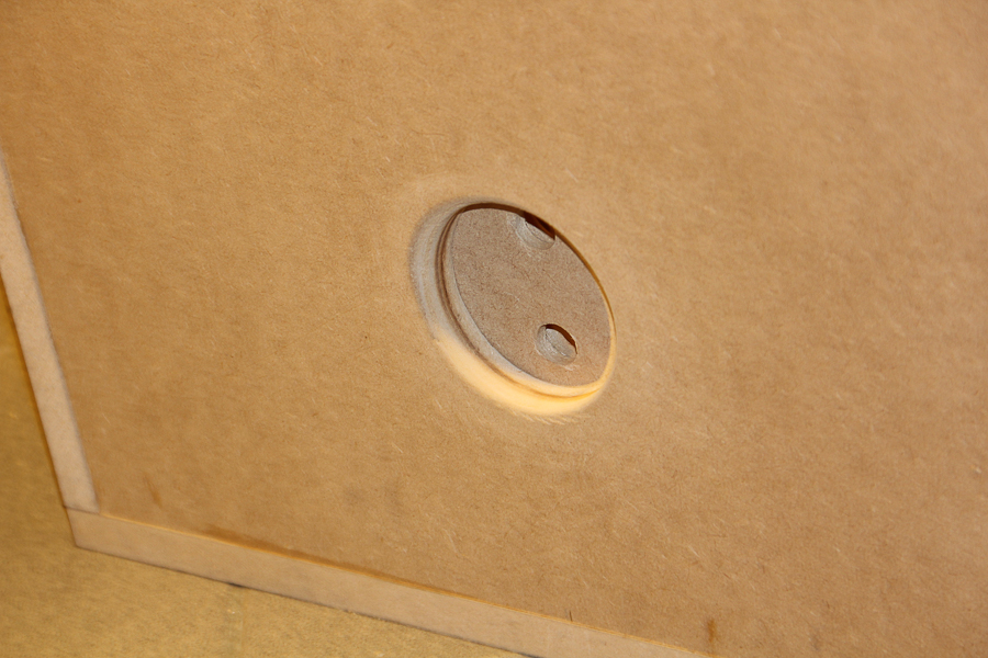
T-nuts for woofers
to be continued...
Later, when I'll have put some money aside (once again) for the 4pi project, I'll upgrade them with diy passive crossovers, following the schematics of Waynes design.
I bought the B&C de250 drivers in Belgium, Wayne shipped 2 H290C horns (they sound great! even without CD compensation), and I could buy 2 second hand JBL 2226 drivers.
horns arrived!
Bought 2 MDF panels (240cm * 122cm, 1 speaker = 1 panel) and started with the bass reflex ports:
strengthened the opening for the JBL driver
glued the bassport to the front baffle
the cabinets are rising!
Installing braces between woofer and tweeter (for isolation material)
T-nuts for woofers
to be continued...
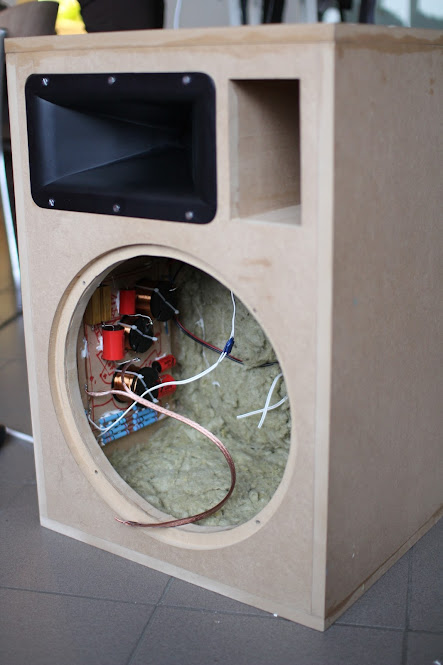
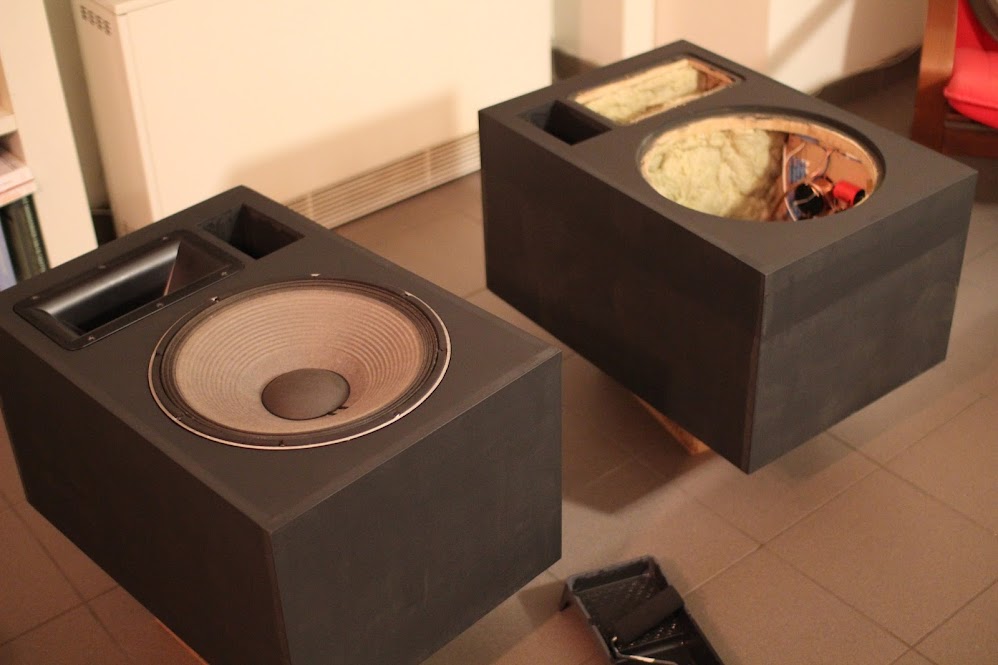
the speakers are almost finished! I'm waiting for the x-over components, for now, the speakers are driven with active X-over. Some pictures:
Soldered some cables and connections
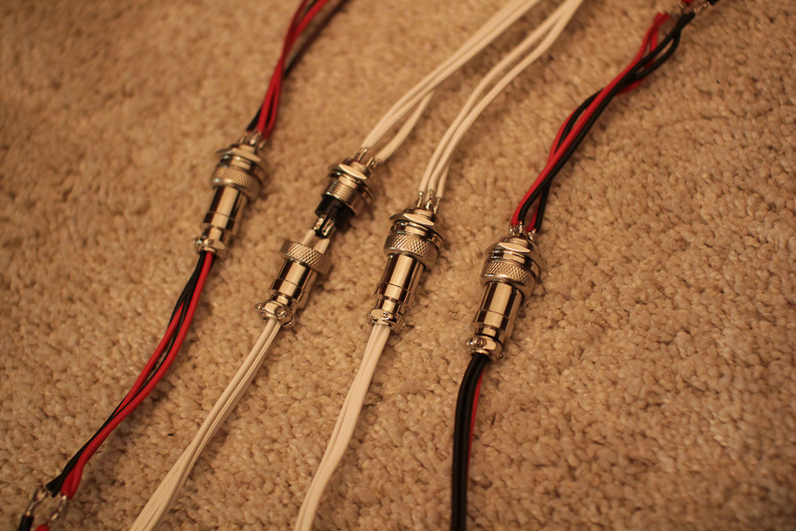
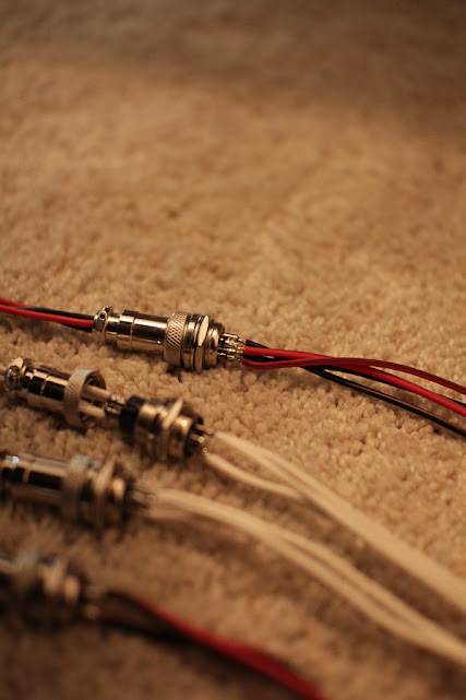
Built in the connectors

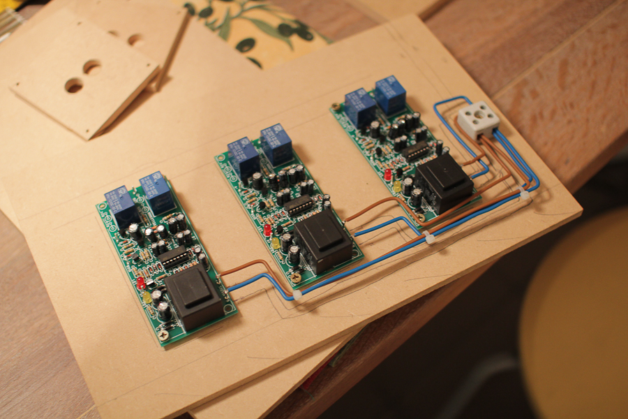
As my amp has no delay relay, I built 3 circuits (2 circuits are used for the 4pi speakers) that delay the signal 6 seconds when the amps are turned on.
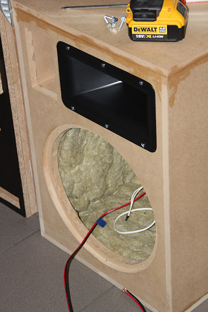
Cut the insulation in parts and glued the insulation in the cabinets:

Old vs new

Nearly finished:
to do:
- glue has to be removed
- cabinets have to be painted (dark grey)
- passive X-over has to be installed
The cabinets fit now in a shelf. Later on, I'll glue thin panels of walnut wood to the side baffles and the back. (dark grey front baffle will stay as is)
Soldered some cables and connections
Built in the connectors
As my amp has no delay relay, I built 3 circuits (2 circuits are used for the 4pi speakers) that delay the signal 6 seconds when the amps are turned on.
Cut the insulation in parts and glued the insulation in the cabinets:
Old vs new
Nearly finished:
to do:
- glue has to be removed
- cabinets have to be painted (dark grey)
- passive X-over has to be installed
The cabinets fit now in a shelf. Later on, I'll glue thin panels of walnut wood to the side baffles and the back. (dark grey front baffle will stay as is)
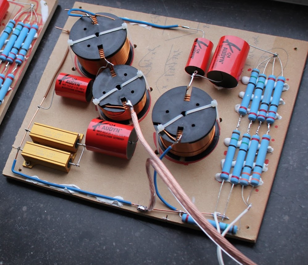
Hello, I finished the 4pi speakers. Passive x-overs are installed (there IS a difference with the active x-over! ), the glue is removed and the cabinets are painted.
I guess this thread is not the right place for a build thread, but it is thanks to the comments of other members in this thread that I decided to make the 4pi speakers, so I'll leave it here.
The last pictures:
- ordered the components for the cross-overs and tried to make a good looking assembly
- Painted the cabinets
- cabinets in place

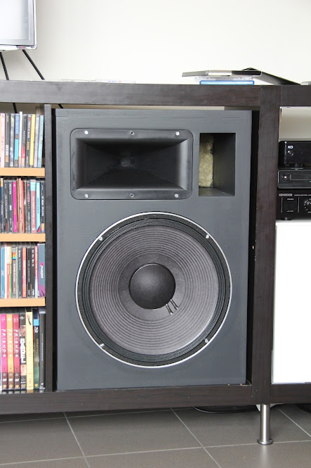
It might be better to add an acoustically transparent fabric behind the BR-port, because the insulation popping out isn't really good-looking.
BUT: Great sound! Detailed, rich and powerfull! I went to an audio shop and listened to a lot of speakers that even cost more, but the dynamics of those speakers didn't equal the 4pi's!
), the glue is removed and the cabinets are painted.I guess this thread is not the right place for a build thread, but it is thanks to the comments of other members in this thread that I decided to make the 4pi speakers, so I'll leave it here.
The last pictures:
- ordered the components for the cross-overs and tried to make a good looking assembly
- Painted the cabinets
- cabinets in place
It might be better to add an acoustically transparent fabric behind the BR-port, because the insulation popping out isn't really good-looking.
BUT: Great sound! Detailed, rich and powerfull! I went to an audio shop and listened to a lot of speakers that even cost more, but the dynamics of those speakers didn't equal the 4pi's!
Last edited:
- Status
- This old topic is closed. If you want to reopen this topic, contact a moderator using the "Report Post" button.
- Home
- Loudspeakers
- Multi-Way
- Upgrading drivers