But group delay is a time delay. A delay at certain frequencies relative to other frequencies, and is caused by a difference in the slope of the phase at different frequencies. It's all intertwined and inseparable.My intended point is that I don't know how you can introduce a significant GD anomaly without simultaneously creating a delay effect. How do you separate the two? How do you say the effect is from GD and not TD or phase shift?
Say you had a 1Khz 24dB/oct L/R crossover that was electronically summed to a flat amplitude response. (no speakers involved) Over most of the audio range you'd have essentially zero group delay, but around 1Khz the delay would peak up to something like 0.5ms (approximate off the top of my head figure) with a nice bell shaped curve. Over that narrow range of frequencies there is a time delay in arrival of the signal relative to other frequencies.
In an acoustic environment you also have a fixed propogation delay through the air from drivers to mic/ear due to distance which is constant for all frequencies, (assuming time aligned drivers) so in taking a group delay measurement you usually choose the frequencies with the shortest delay as your arbitary zero reference, with additional delay being a positive figure.
Last edited:
I find that bass and kettle drums in classical music have a much better sound when the woofs are flat to 20HZ, rather than only 40HZ. They might make a good GD test. Perhaps it's the way the harmonics mix that's going to be noticeably different (?).I can try some other stuff, can anyone suggest a music sample to alter? The Steely Dan had pretty good energy below 100Hz, but not all the way down to 20. Not many do.
If I understand correctly, GD is not the delay itself, but the rate of change of that delay or phase shift (?)But group delay is a time delay. A delay at certain frequencies relative to other frequencies, and is caused by a difference in the slope of the phase at different frequencies. It's all intertwined and inseparable.
This is from Is Linear Phase Worthwhile?
I pontificate on many of the points discussed here and also show 'real' delay in various xover circuits and other stuff.
The important point about Minimum Phase transfer functions is that there will exist another 'real life' Min. Phase function that will exactly correct it WITHOUT ANY RESULTANT DELAY.
I also make the point that the concept of Group Delay only makes sense if either
Also Listening Tests.
I pontificate on many of the points discussed here and also show 'real' delay in various xover circuits and other stuff.
The important point about Minimum Phase transfer functions is that there will exist another 'real life' Min. Phase function that will exactly correct it WITHOUT ANY RESULTANT DELAY.
I also make the point that the concept of Group Delay only makes sense if either
- the amplitude response is constant over the frequency range of interest
- or the group delay is constant over the frequency range of interest
Also Listening Tests.
Attachments
Not quite.If I understand correctly, GD is not the delay itself, but the rate of change of that delay or phase shift (?)
Group delay is delay plotted versus frequency. It's the rate of change of phase. (or the slope of the phase graph) As I said before, its the first derivative of phase.
Imagine you measure the response of a driver at a certain distance and our imaginary driver has a nice flat amplitude response.
The further the distance from the speaker to mic, the steeper the phase curve will be, because a constant time delay will cause more phase shift the higher in frequency you go. If there is no group delay the phase shift will be a straight line on a linear frequency axis.
That's why the steepness of the phase curve is equivalent to time delay.
Now imagine what happens when we cross over between two drivers, one of which is closer to the mic than the other. Well into the passband of the closer driver the steepness of the phase curve will be a certain slope, however when we fully cross over to the further away driver the phase curve must be steeper because of the additional distance (delay) causing more phase shift per Hz. This causes a transition from less to more group delay as we transition from one driver to the other, therefore a shelf in group delay due to the physical offset.
It's not quite that simple though because the all pass response of the summed high pass and low pass also causes a temporary increase in phase slope around the crossover due to the way the phase of the two sources sum, even if the drivers were time aligned. The delay is purely electrical but just as real.
So what you end up with time misaligned drivers crossing over to each other is a shelf between the two frequency ranges but also with a peak in group delay near the transition region that goes above the higher side of the shelf.
See below for an example of a 3rd order crossover at 4Khz with the tweeter about 20mm closer than the midbass. The measurement is only accurate down to about 500Hz due to the gating time but you can clearly see the peak in GD as well as the shelf on either side.
The reason why the curve is so smooth despite being an acoustic measurement is that its actually excess group delay, which factors out the group delay related to amplitude response changes.
PS I'd forgotten just how small the group delay is in typical crossover arrangements, its far below the 0.5ms guess I suggested earlier, with the group delay from the 3rd order crossover being less than that caused by the 20mm error in driver alignment. In this example about 0.1ms from the acoustic alignment error and a further 0.05ms from the crossover itself.
Attachments
Last edited:
In an acoustic environment you also have a fixed propogation delay through the air from drivers to mic/ear due to distance which is constant for all frequencies, (assuming time aligned drivers) so in taking a group delay measurement you usually choose the frequencies with the shortest delay as your arbitary zero reference, with additional delay being a positive figure.
not only fixed delay due to mic distance,also reflexions come later to the listener,it depends of the wall absorption,some region can be delayed more than other.(reverberation time ).
but it's a quite complex for me.acoustic treatement,improvement needs in-depth knowledge (and wiseness
 ).
).that's why i think,we need to correct loudspeaker before (spl and phase (word "delay" is most suitable)).
and in a second time,correct (or trying to ) the room,DRC...etc..
Last edited:
This is from Is Linear Phase Worthwhile?
I pontificate on many of the points discussed here and also show 'real' delay in various xover circuits and other stuff.
The important point about Minimum Phase transfer functions is that there will exist another 'real life' Min. Phase function that will exactly correct it WITHOUT ANY RESULTANT DELAY.
I also make the point that the concept of Group Delay only makes sense if either
References, maths etc in the paper.
- the amplitude response is constant over the frequency range of interest
- or the group delay is constant over the frequency range of interest
Also Listening Tests.
Convolution of any two minimum phase functions with group delay, which they all have, results in minimum phase function with group delay. That first sample in each impulse is peak means propagation time for maximum output sample is minimum. A class of minimum phase filters exist for which convolution of their amplitude conjugates returns perfect IR: parametric EQ, which is monotonic to a single frequency. The higher the Q, the longer they ring. These filters may be summed aligned to filter sample peaks (1st sample every time), but now we define minimum phase because each frequency is at same phase at 1st sample. The lower the frequency, the longer the time before amplitude peak in minimum phase filter. Summed series of parametric filters may be used to flatten frequency response, with smoothing of phase/group delay, but this leaves fundamental high pass phase behavior of drivers to deal with, and an information system that won't pass a square wave without waveform distortion.
If you want to test this by listening, I've made some files for you. You'll recognize the song.It has good content below 100Hz
The audio file was split into 2 parts, one was 4th order low pass filtered at 100Hz, the other high pass filtered at 125Hz. The spread is because the filter is butterworth and combines flatter with the slight spread. The file was then recombined. Phase is rotated 180 degs at 110Hz (because of the spread) and continues down to 360 degs at DC. Or vice-versa, depending on how you look at it.
The files are here, you can download them. About 1 min long, each 2.2meg in 320KBS mp3 format. Can you tell which was manipulated, and which was not? Or at least if there is a difference or not between the 3?
My MP3 file player (Audition) also shows the waveform, so I couldn't do the ABX test because the differences were obvious to the eye. Given that, I tried listening to the snare drum -- a previous phase rotation test at 250 Hz was more obvious on that particular instrument over others, but not this time. My guesses were no better than chance.
On the other hand, listening to the kick drum during the first few seconds, and its separation from the bass guitar, did show a subtle difference. The kick in one file was not as "slammy" and also less distinct from the bass. I could rapidly control-tab for a few seconds between the two files (a crude randomiser), and upon listening carefully still be able to tell which was which with my eyes closed.
I'll PM Pano to tell him which one I thought was processed and which one was clean.
Gear used: 2010 MacBook Pro, Sennheiser HD800.
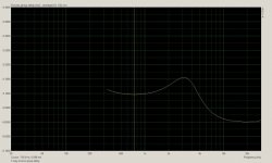
Yes, percussion on track is only sound with hard transient. Pano's Butterworth filtering for this is form of shelving filter, and from group delay perspective looks something like this:

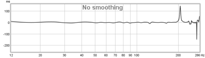
Very mild compared to temporal aberration with speaker in living room measured at listening position:

Above is raw cardioid woofer setup with previously posted DSP correction results in #36
Very mild compared to temporal aberration with speaker in living room measured at listening position:
Above is raw cardioid woofer setup with previously posted DSP correction results in #36
Yes, percussion on track is only sound with hard transient. Pano's Butterworth filtering for this is form of shelving filter, and from group delay perspective looks something like this:
View attachment 321838
Very mild compared to temporal aberration with speaker in living room measured at listening position:
View attachment 321837
Above is raw cardioid woofer setup with previously posted DSP correction results in #36
You can't directly compare these two graphs (for audibility) though - you're comparing apples to oranges because the first one is group delay that is caused only by excess phase (the frequency response is still flat with pano's summed filters) but the second one is clearly group delay that is caused largely by amplitude response non flatness, eg group delay that is due to both minimum phase and excess phase components but with minimum phase components dominating.
Therefore you can't tell anything about how "audible" this group delay is in comparison to the first, because most of it is caused by a very non-flat amplitude response which will be audible in and of itself.
As I said in my previous post, lumping together the audibility of group delay and excess group delay (pano's test has only excess group delay) has been going on throughout the thread and only serves to confuse the issue.
The only valid test to determine whether group delay by itself is audible is to maintain identical amplitude responses which means we are really studying excess group delay, not group delay.
Any test where we're altering the frequency response to produce group delay proves nothing except that frequency response alterations are audible...
Out of interest, try showing us the excess group delay instead of group delay on your bottom measurement, you'll find that across most of the bass region the excess group delay will be relatively flat even in a room, but there may be one or two frequencies where it peaks up really high, typically where there is either a notch in the amplitude response or where the reflections are higher in amplitude than the direct signal...this is useful because it shows us where (with the current speaker configuration and listening position) we cannot EQ out the response error with normal minimum phase EQ...
Last edited:
You can't directly compare these two graphs (for audibility) though - you're comparing apples to oranges because the first one is group delay that is caused only by excess phase (the frequency response is still flat with pano's summed filters) but the second one is clearly group delay that is caused largely by amplitude response non flatness, eg group delay that is due to both minimum phase and excess phase components but with minimum phase components dominating.
Therefore you can't tell anything about how "audible" this group delay is in comparison to the first, because most of it is caused by a very non-flat amplitude response which will be audible in and of itself.
As I said in my previous post, lumping together the audibility of group delay and excess group delay (pano's test has only excess group delay) has been going on throughout the thread and only serves to confuse the issue.
The only valid test to determine whether group delay by itself is audible is to maintain identical amplitude responses which means we are really studying excess group delay, not group delay.
Any test where we're altering the frequency response to produce group delay proves nothing except that frequency response alterations are audible...
Out of interest, try showing us the excess group delay instead of group delay on your bottom measurement, you'll find that across most of the bass region the excess group delay will be relatively flat even in a room, but there may be one or two frequencies where it peaks up really high, typically where there is either a notch in the amplitude response or where the reflections are higher in amplitude than the direct signal...this is useful because it shows us where (with the current speaker configuration and listening position) we cannot EQ out the response error with normal minimum phase EQ...
All most my exact point. Pano's first phase distorting filter is of same type all ready present in most recording/playback chains and speakers.
You can't know what a square wave sounds like until you can produce it acoustically. Real sounds in music all start with causal moment, with minimum phase and very quickly morph to non-minimum phase as rest of instrument starts radiating, followed by immediate environment of instrument. So circle the wagons; compare waveform recorded of instrument, that has been corrected for minimum phase effects of microphone system, and what this sounds like played back on speaker v real instrument.
When I analyze my own recording and playback chain, it readily shows minimum phase impact on content <200Hz, providing basis of masking very effect being discussed, even when using expensive headphones.
Now here is confusion:
As I said in my previous post, lumping together the audibility of group delay and excess group delay (pano's test has only excess group delay) has been going on throughout the thread and only serves to confuse the issue.
Pano's test with "Josie" is convolution with sum of two minimum phase filters, indexed to causal start of each resulting in perfectly minimum phase filter. Zero excess phase.
Points about excess phase are well taken into consideration with corrections I produce. In case of posted sub setup room response is speaker response at listening position. This is excess phase of raw cardioid sub:

In above first big excess phase event is above range of sub. For main speaker measurement and correction due consideration is given, and excess phase between two measurements is adjusted for when integrating filters from different measurements.
Fully corrected system is basis for comparison, and I find my setup reproduces waveform of source to much greater fidelity than any uncorrected system I've worked with.
Not true at all, unless you have a different definition of minimum phase to everyone else. Two minimum phase filters can and usually do sum to a non-minimum phase result.Now here is confusion:
Pano's test with "Josie" is convolution with sum of two minimum phase filters, indexed to causal start of each resulting in perfectly minimum phase filter. Zero excess phase.
Take a 2nd order L/R low pass and high pass. Individually they are minimum phase. Sum their outputs together and the amplitude response is perfectly flat however the sum is not minimum phase because there is a 180 degree total phase rotation from low frequencies to high frequencies. It forms an all-pass filter.
The excess phase / excess group delay without any change of amplitude response was the whole point of pano's test.
Not true at all, unless you have a different definition of minimum phase to everyone else. Two minimum phase filters can and usually do sum to a non-minimum phase result.
Take a 2nd order L/R low pass and high pass. Individually they are minimum phase. Sum their outputs together and the amplitude response is perfectly flat however the sum is not minimum phase because there is a 180 degree total phase rotation from low frequencies to high frequencies. It forms an all-pass filter.
The excess phase / excess group delay without any change of amplitude response was the whole point of pano's test.
You have to be careful here with the term "sum". It sometimes means "cascade", in which case the two MP filters will always yield a MP result and "adding" different signal paths, which does not guarantee a MP result from two MP filters. I see confusion above in this regard.
Points about excess phase are well taken into consideration with corrections I produce. In case of posted sub setup room response is speaker response at listening position. This is excess phase of raw cardioid sub:
In above first big excess phase event is above range of sub. For main speaker measurement and correction due consideration is given, and excess phase between two measurements is adjusted for when integrating filters from different measurements.
Fully corrected system is basis for comparison, and I find my setup reproduces waveform of source to much greater fidelity than any uncorrected system I've worked with.
Impressive !
where can we see this cardiod subwoofer ? any pictures around there ?
what kind of DSP are you using ? (standalone or computer ).
You have to be careful here with the term "sum". It sometimes means "cascade", in which case the two MP filters will always yield a MP result and "adding" different signal paths, which does not guarantee a MP result from two MP filters. I see confusion above in this regard.
Wouldn't cascading of two filters be multiplication of the transfer functions instead of algebraic summing ?
In any case, given the context of pano's test signal I can't see how there could be any confusion, the result of cascading a high and low pass filter is never going to be an all-pass with a flat amplitude response, which was a key part of the test.
What I was attempting to duplicate was a 4th order HP and LP recombined, as they would be in the air. Is this different from combining them electrically or in software?
Nope, at least not on the design axis with the drivers time aligned. Non time aligned drivers or going off the vertical axis would obviously introduce a time delay between the two (which you could also simulate) while both horizontal and vertical off axis would change the individual transfer functions a bit due to off axis beaming of the drivers, thus the summed off axis result.
So it would be a valid test of the perceived on axis response but probably not of the changes to the reverberant field or early reflections. (since summing in air is only the same as the electrical summing on axis)
Early sidewall reflections would only be affected by the changes due to driver beaming mind you, not by differences in delay, so for a speaker with uniform horizontal off axis performance it would be representative of early sidewall reflections too.
Last edited:
I tried to hear a difference between the 3 files,headphone and loudspeaker.
...nothing.
here's the modification on the file
it's about 4-5 ms delay below 125 Hz.
it's like the woofer is 4.7 fts stepping back.
24 db/oct recombined.
and the group delay modification
...nothing.
here's the modification on the file
it's about 4-5 ms delay below 125 Hz.
it's like the woofer is 4.7 fts stepping back.
24 db/oct recombined.
An externally hosted image should be here but it was not working when we last tested it.
and the group delay modification
An externally hosted image should be here but it was not working when we last tested it.
Last edited:
- Status
- This old topic is closed. If you want to reopen this topic, contact a moderator using the "Report Post" button.
- Home
- Loudspeakers
- Multi-Way
- We can not hear group-delay under 100Hz?