
Not at 100Hz.Thanks Simon and Thierry.
If we really do hear something, it might be the off-axis response faults, more than the filter function.GD itself. What do you think?
 For some reason when I wrote my reply it went completely out of my mind that your test was centred around 100Hz, so of course off axis response due to beaming, reverberant field etc that I was talking about is all meaningless at those low frequencies. It's really much higher frequencies that I was thinking about like midrange to tweeter crossovers.
I think its just that we simply aren't as sensitive to group delay at low frequencies as we are at high frequencies, with sensitivity peaking in the upper midrange. This much is well proven from the various literature. From your quick test people are struggling to detect 5ms at bass frequencies, yet thresholds at upper midrange are more like 1ms..
I really don't think modest amounts of group delay at bass frequencies is the big bogey man that many people think, we just don't have that much temporal resolution in our perception at those low frequencies...(with most of it coming from the harmonics of the bass notes)
maybe a nearfield measurement at 60° vertical off axis could shows a little null.(but ears...).
as said before group delay in listening room reach 30-60 ms or more.
lenght wave at this FR are omnidiectionnals.
but why i do not feel any difference with a headphone ???
next try,a recombined file at 1kHz ?
).as said before group delay in listening room reach 30-60 ms or more.
lenght wave at this FR are omnidiectionnals.
but why i do not feel any difference with a headphone ???
next try,a recombined file at 1kHz ?
Last edited:
Not at 100Hz.
I think its just that we simply aren't as sensitive to group delay at low frequencies as we are at high frequencies, with sensitivity peaking in the upper midrange. This much is well proven from the various literature. From your quick test people are struggling to detect 5ms at bass frequencies, yet thresholds at upper midrange are more like 1ms..
I really don't think modest amounts of group delay at bass frequencies is the big bogey man that many people think, we just don't have that much temporal resolution in our perception at those low frequencies...(with most of it coming from the harmonics of the bass notes)
With respect, I disagree wrt GD in low frequencies. It took a certain amount of listening before I could define a difference, but once my ears were trained it was relatively simple to discern which file was which.
The first few harmonics of a percussion instrument are the clearest test to me of phase rotation at a given frequency: kick drums for 100 Hz, snares for 250 Hz, although I haven't yet tested other rotation frequencies with things such as cowbells, claves, or triangles.
Steadier-state instruments such as organ or voice don't seem to be as obvious. I have a theory as to why that might be the case, and it also predicts we are not likely to hear phase differences above 1 kHz so long as the reverberant field is the same.
Not true at all, unless you have a different definition of minimum phase to everyone else. Two minimum phase filters can and usually do sum to a non-minimum phase result.
Take a 2nd order L/R low pass and high pass. Individually they are minimum phase. Sum their outputs together and the amplitude response is perfectly flat however the sum is not minimum phase because there is a 180 degree total phase rotation from low frequencies to high frequencies. It forms an all-pass filter.
The excess phase / excess group delay without any change of amplitude response was the whole point of pano's test.
Take Linkwitz-Riley 4th order 24dB/oct 1kHz crossover pair, high pass and low pass have identical phase. All pass sum has identical phase. 360 degrees. It is completely minimum phase system with flat frequency response:
Wrapped display of phase:

Unwrapped phase:

Each order in filter places 90 degrees of phase shift from DC to Nyquist. Typical Cartesian phase plot show +/-180 degrees with vertical broken dashed line showing continuation of plot; this is not a 180 degree phase inversion.
I tried to hear difference with all-pass (LPF+HPF) 24DB/oct @1Khz
loaded in convolver,bypass on the fly,with a headphone.
...nothing to notice.Impossible to hear the difference.
delay added below 1 Khz is less than 0.5ms.
need to try with 2 or 3 ms
loaded in convolver,bypass on the fly,with a headphone.
...nothing to notice.Impossible to hear the difference.
delay added below 1 Khz is less than 0.5ms.
need to try with 2 or 3 ms
An externally hosted image should be here but it was not working when we last tested it.
Take Linkwitz-Riley 4th order 24dB/oct 1kHz crossover pair, high pass and low pass have identical phase. All pass sum has identical phase. 360 degrees. It is completely minimum phase system with flat frequency response:
Wrapped display of phase:
View attachment 322061
Unwrapped phase:
View attachment 322062
Each order in filter places 90 degrees of phase shift from DC to Nyquist. Typical Cartesian phase plot show +/-180 degrees with vertical broken dashed line showing continuation of plot; this is not a 180 degree phase inversion.
Sorry, but you don't seem to be listening to what I'm saying. The individual high pass and low pass sections are minimum phase by themselves. The summed response of a 4th order L/R crossover (or indeed any order 2nd or above) is not minimum phase. I don't know how I can be any clearer than that.
Please sum the response of the low and high pass sections and show me how it can be minimum phase because it is not. This is basic stuff.
Pictures in previous post are very clear; showing overlays of phase for low pass, high pass, and all pass as sum. Being all the same phase, all starting at the same time
Here are IR responses of Linkwitz-Riley 4th order 24dB/oct 1kHz crossover pair:
high pass:

low pass:

all pass as sum:

above in overlay view:

What about all pass IR pictured above isn't minimum phase?
"what about all pass IR pictured above isn't minimum phase?"
The summed response of LP+HP ( LR4) is perfectly flat in amplitude but phase turns, giving a all-pass. Amplitude and phase in the sum are no longer linked by Hilbert's transform as were, separetely, LP and HP.
crd
The summed response of LP+HP ( LR4) is perfectly flat in amplitude but phase turns, giving a all-pass. Amplitude and phase in the sum are no longer linked by Hilbert's transform as were, separetely, LP and HP.
crd
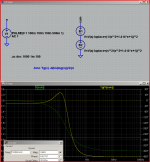
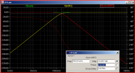
LR4 has 360 degrees phase rotation (right axis, green dotted line)
normalized plot - fxo = 159 mHz (1 rad/s)
the green sum frequency response amplitude is flat at 1.0 - under the cursor dotted line in the 1st plot
Tg=Group delay (yellow, left axis) is in seconds for this low freq - would be x10 ms for 160 Hz XO frequency
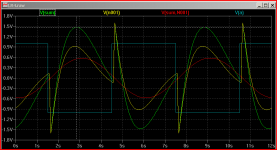
the 1/6 Hz square wave .tran green sum shows lots of phase error
red LP is nearly a sine in the .tran plot - but with basically inverted polarity
normalized plot - fxo = 159 mHz (1 rad/s)
the green sum frequency response amplitude is flat at 1.0 - under the cursor dotted line in the 1st plot
Tg=Group delay (yellow, left axis) is in seconds for this low freq - would be x10 ms for 160 Hz XO frequency
the 1/6 Hz square wave .tran green sum shows lots of phase error
red LP is nearly a sine in the .tran plot - but with basically inverted polarity
Attachments
Last edited:
Yes, but phase response of LP and HP are identical.
Imo, they just seem to be, but are not : 360° between lp and hp is a reality
witch appears in transcient response of the sum. It's a bit like, for the sum, 360° had been lost.
crd
LR4 has 360 degrees phase rotation (right axis, green)
normalized plot - fxo = 159 mHz (1 rad/s)
the green sum frequency response amplitude is flat at 1.0 - under the cursor dotted line in the 1st plot
Tg=Group delay (yellow, left axis) is in seconds for this low freq - would be x10 ms for 160 Hz XO frequency
the 1/6 Hz square wave .tran green sum shows lots of phase error
red LP is a sine - but with basically inverted polarity
......and this is why I swear by 1st order filters.
the probelm with 1st order is that the amplitude of motion for the tweeter never goes down from the XO - only the from the tweeter's own electroacoustic/mechanical mass-spring HP
so you get more motor/spider/amplitude distortions from the driver below the XO freq, can cause higher IMD, Doppler in the passband
and you need lots of driver response overlap so the tweeter driver's HP doesn't cause a audible dip, or LF driver cone breakup resonances don't give bumps above the XO freq
Last edited:
This thread has covered a lot of ground and I can't remember all of it so if I missed something, (likely) please forgive me. I'm not a strong math guy but here goes:
Group Delay or Envelope Delay seems to be a simple concept and at once something that I haven't really been able to clearly wrap my head around. The simple part, when what goes in comes out spread over time, that is group or envelope delay as compared to if it all came out at once but late, that is latency. Latency is functionally the same as excess group delay as in time of flight from a driver under test to the mic. Right?
Is group delay one of those math functions that breaks down when approaching infinity or zero? To me it seems like group delay goes infinite when frequency approaches zero.
There was a discussion on Pro Sound Web a while back where someone stated something to the effect that: "It seem counter intuitive that a woofer has an increasingly harder time tracking a signal at low frequencies than high, but that's the way it works." I think that's wrong, so I did some experimenting.
I set up my dual channel measurement system TEF, with a Techron 7570 DC coupled 2kW power supply driving a new JBL 2242 in free air with a mic on TEF Channel One in very close proximity to the dust cap and my laser position sensor on TEF Channel Two right next to the mic "lookiing" at the dust cap. I also connected my four channel Tektronic scope to the output of the amp, the mic, and the laser for visual tracking as well. I can set cursers on the scope and get real time and or degrees between channels, like the amp and laser position.
The short of what I found was the driver physcally follows the signal at low frequency and gets later as the frequency increases. I started at 0.25Hz to be sure I wasn't a cycle off. So, if the driver gets later and later as the frequency increases, why does the "measured" group delay increase as frequency decreases if it is not a math thing? And if it's just a math thing, why should I worry about it?
I took a bunch of pictures of the set up and can't find them, I can recreate it and think I should revisit this.
Any thoughts?
engineers usually try to use math to model reality
a finite time delay becomes an infinitesimal phase at infinitely low frequency - so that works out fine
in the normal operating range of dynamic loudspeakers the SPL output is proportional to cone velocity
below the mass-spring resonance a dynamic driver displacement is proportional to the coil current caused electromagnetic force pushing against the spring constant of the spider/suspension (and the enclosed air for sealed box speaker)
in the working range for audio output, above the mass-spring resonance, the mass of the cone+voice coil rolls off the amplitude, this inertia and electromechanical coupling causes the the cone velocity to become mostly proportional to AC drive voltage
Last edited:
This thread has covered a lot of ground ........
Any thoughts?
Sure has......
For your measurements/observations did you look at behavior before and after resonance frequency of driver system?
I do bulk of measurements with exponentially swept sine. Pairing response recording with test sweep shows a lot. In pairing you can look at zero crossings of the waveforms and get near perfect alignment as each pair of zero crossings has unique time interval. Scanning forward/backward shows crests/zero crossings shifting in frequency dependent manner.
Getting all the zero crossing to correspond over desired bandwidth is goal of phase correction. Crest amplitude correction simultaneously is also goal. Waveform fidelity.
For experimental purposes, time delay incurred for processing to get this result is not consideration.
Achieving this result allows creation of reference conditions where questions such as this thread topic may be addressed.
......and this is why I swear by 1st order filters.
1st order filters have perfect transient response, and without time reversal are of no practical use for improving time domain issues inherent in speaker design. The only way to get perfect sum with them in crossovers is to use identical drivers. Beaming of woofers with breakup excitation in overlap region, resonance of tweeters and IMD, driver separation at usable crossover frequency.... Yes, the simple pleasures in doing nothing new and the knowledge that one is experiencing the same speaker performance of sixty years ago.
Just think of group delay as a way to describe the relative delay between different frequencies (the curve of the graph) and latency as a constant offset (like a DC bias on the graph) that introduces a minimum delay upon which that curve rests.Group Delay or Envelope Delay seems to be a simple concept and at once something that I haven't really been able to clearly wrap my head around. The simple part, when what goes in comes out spread over time, that is group or envelope delay as compared to if it all came out at once but late, that is latency. Latency is functionally the same as excess group delay as in time of flight from a driver under test to the mic. Right?
In most applications the overall latency doesn't really matter (we don't care if the sound from our speakers arrives 1ms later if they're 1 foot further away, when there is nothing else to compare them to) so software that measures group delay provides a way to subtract out this latency - in ARTA the settings is "delay for phase estimation", which changes the slope of the raw phase response and thus moves the group delay line up and down a constant offset. (Since group delay is the derivative of phase)
That one's easy to explain. As you found, at very low frequencies the driver displacement moves almost in phase with the electrical input, so your question is why is the sound not in phase at this point, and where is the increasing group delay at low frequencies coming from ?I set up my dual channel measurement system TEF, with a Techron 7570 DC coupled 2kW power supply driving a new JBL 2242 in free air with a mic on TEF Channel One in very close proximity to the dust cap and my laser position sensor on TEF Channel Two right next to the mic "lookiing" at the dust cap. I also connected my four channel Tektronic scope to the output of the amp, the mic, and the laser for visual tracking as well. I can set cursers on the scope and get real time and or degrees between channels, like the amp and laser position.
The short of what I found was the driver physcally follows the signal at low frequency and gets later as the frequency increases. I started at 0.25Hz to be sure I wasn't a cycle off. So, if the driver gets later and later as the frequency increases, why does the "measured" group delay increase as frequency decreases if it is not a math thing? And if it's just a math thing, why should I worry about it?
Your misunderstanding is that sound is produced by (and therefore in phase with) the displacement of the cone - it isn't. It's produced by the acceleration of the cone, so the SPL is in phase with the acceleration. Because the woofer is a harmonic oscillator the electrical input and acceleration are in phase above the mechanical resonance.
Thus a long way above the resonance input signal and SPL are in phase because input signal and acceleration are in phase. A long way below the resonance (near DC) the acceleration is 180 degrees out of phase with the input signal thus so is the SPL, and that 180 degree phase shift (for a closed box) is where your group delay comes from at low frequencies.
The harmonic oscillator formed by the woofer mass, compliance and damping mimics a 2nd order high pass filter.
There's a really good image posted by bolserst in post 114 in the following thread that shows the relationship between acceleration/velocity/displacement, and amplitude/phase for each:
http://www.diyaudio.com/forums/multi-way/201226-drivers-behave-mass-spring-3.html#post2804039
Note: an earlier version of the image has a mistake in it which was corrected for post 114.
Barley, I think you need to do some homework on the definition of Minimum Phase.Yes, but phase response of LP and HP are identical. Thus sum is minimum phase, identical to LP and HP components. This is beauty of Linkwitz-Riley transform. Convolution of a Butterworth filter with itself, cascading stages, same thing.
There are several possible definitions.
One is that the Amplitude & Phase responses are uniquely linked via various Hilbert Transforms [*]. ie for a Minimum Phase transfer function, there is only ONE Phase response which corresponds to its Amplitude response. For a flat Amplitude response, the unique phase response is 0 (or 180) phase.
All-pass networks are (by definition) non-Minimum Phase.
Bear in mind also what the term Minimum Phase implies. Alternative titles might be Minimum Group Delay, Minimum Smear or Minimum Energy Delay.
A Minimum Phase transfer function will have the least Delay, Smear of any transfer function with the same amplitude response. You can dream up your own definition of Delay, Smear etc and try various phase responses to see if you can get less or better Delay, Smear etc compared with a Minimum Phase response.
[*] Various cos there is Log amplitude, Lin amplitude, Re & Im, exponential versions ... etc.
_________________
Group Delay is by definition -d(phase)/d(freq).
But as I said earlier (and also by Dick Heyser & Bode), it corresponds to Envelope Delay (ie appear to delay a group of frequencies) only under certain conditions.
- when GD is constant over the frequency range of interest OR
- when amplitude is constant over the frequency range of interest.
One property (and another definition) of a Minimum Phase transfer function is that there will exist another Minimum Phase transfer function that will EQ this perfectly WITHOUT ANY RESULTANT DELAY. Both these functions are physically realisable to any degree of accuracy you wish or are prepared to pay for.
As the final EQ'd circuit has NO DELAY, it is somewhat misleading to imply the original Minimum Phase circuit has a 'delay' (though it will have a GD as defined by the above math expression) unless your matching EQ circuit has real negative delay (ie a time machine).
Having said that, the concept of GD does have use in certain Minimum Phase circuits (that fullfill either of the above requirements) but these are usually at RF.
"Is Linear Phase Worthwhile?" has examples of both and also shows how excess phase (eg an All-pass network) DOES result in true delay for audio.
___________________
But to get back to the original post .. My own work in the early 80's shows a 1ms pulse repeated at 500 - 100Hz is audibly changed by 6 x 1st All-pass networks at 1kHz in a Double Blind bla bla Listening Test.
Other work suggests that Absolute Phase of carefully recorded Bass Drums can be reliably detected.
But today, we have the possibility of much better recordings (though unfortunately, most modern recordings are worse than 30 yrs ago
)I think there is a strong possibility that Excess Phase is detectable below 100Hz. The maximum sensitivity is only slightly above that freq.
Whether it is worth correcting is another issue but I would very much like to conduct Double Blind ABC or ABX tests on this as I did in the early 80's ... especially on music.
Last edited:
- Status
- This old topic is closed. If you want to reopen this topic, contact a moderator using the "Report Post" button.
- Home
- Loudspeakers
- Multi-Way
- We can not hear group-delay under 100Hz?