I have a suspicion that all that happens is that the amp delivers more power, but the same amount still goes through the tweeter Just more goes off to earth through the shunt... The impedance is constant but nothing changes other than the amp delivering more power (the extra going through the shunt) at that frequency.
I Just did a sim and absolutely no difference between the LCR and No LCR as far as spl is concerned.
I have a feeling I've been through this before
Tony.
I Just did a sim and absolutely no difference between the LCR and No LCR as far as spl is concerned.
I have a feeling I've been through this before
Tony.
Sorry guys. What determines the excursion is the voltage across the terminals of the tweeter. PERIOD. The only function of the LRC is to flatten the driver's Z. The only way that affects the voltage across the tweeter's terminals is by the way it affects the crossover's transfer function. If the same voltage transfer function can be obtained with and without the LRC (by changing the crossover component values) then the excursion is the same with and without the LRC. Low impedance in the return path yielding greater damping is not accurate. As I stated before, if the same acoustic output is obtained (which means the same voltage applied across the tweeter terminals) everything is the same, excursion, damping, everything.
Remember, this is a minimum phase response of a linear, time invariant system (for the most part). It's frequency and impulse response are related by the FFT. So if you have the same frequency response you have the same impulse response and two linear systems with the same impulse response have the same transient response and damping.
The only unresolved question is whether or not the exact same transfer function can be obtained with and without the LRC. In the passive case it is possible that you may not be able to make them exact. But if you go with an active crossover it should be apparent that the voltage across the tweeter's terminals is not a function of the LRC.
So here we are again. The LRCs effect on excursion is only a result of how it affects the Z load seen by the rest of a passive crossover, and how that difference in Z affects the crossover transfer function. But the LRC has no direct effect on excursion by itself.
I think part of the confusion is due to the common belief that a resistance in series with a driver increases the driver's Q. That is not correct. The driver's Q does not change. What changes is the system Q. The system is the driver + series resistance. This idea leads to the belief that a high return path impedance leads to poor damping of a tweeter (or other driver). That is not correct either because, again, you have to look at the complete system. Certainly it would appear that a high return path Z would reduce the electrical damping of the tweeter. Taken alone, that is true. But what is ignored by that simple observation is that there is energy stored in the crossover that must also be dissipated. Some of that energy is dumped in the amplifier's source resistance. Some is dumped in the driver voice coil. The result is that the damping of the system is that determined by the transfer function of the voltage across the driver's terminals.
Let's look at an active system driven by a true voltage source, for example. With the driver connected directly to the amp there is no argument about what the return path Z is. But now, let's place a high Q boost circuit at the input of the amplifier. Certainly nothing has changed between the amp and driver as they are still directly connected. But now the response of the driver to an impulse rings like a bell at the center frequency of the Q boost. The driver's damping hasn't changed here, but the damping of the system composed of the Q boost + amp + driver has changed drastically at the Q boost center frequency. Add the LRC and nothing changes other than the Z load seen by the amplifier. The point is that you can not look only at the driver; it is the system response that matters and the system response is observed by looking at the output.
It's the same with the LRC in a passive crossover. It is part of a system. It either has an effect on the system response of it doesn't. In cases where it has an effect that effect willbe observed in the output and may alter excursion. In cases where it has no effect (like with the active crossover), there is no change to observe in the system output and there is no chnage in driver excursion. The LRC alone has no effect on excursion.
John I don't know how to lift and "quote" sections of previous posts as I've seen some people do so can I just go back to your 5th paragraph beginning; "I think....etc" where you discuss the stored energy from the x-over and the paths it takes. Granted as far as you go but you omit the ONE element under discussion i.e. the LCR shunt. If that is a path then surely it increases power dissipation as Vifa suggest.
I just feel you are introducing too many distractions and putting up "straw men" to knock down. No one has raised active systems (which I am fully conversant with) and no one is suggested we look at frequency response with 1st order networks etc or series resistance on driver Q.
I simply sought an explanation as to why Vifa ask that the shunt network they propose be inserted across their tweeter "To ensure maximum electrical damping and consequently minimum excursion" and as they go on to say; "This is essential for high power handling." Their words....
Why does this network achieve these goals?
Cheers, Jonathan.
Btw turning in soon so will not see any further post for about 8 hrs......
Hi Tony. Bits are falling into place. Re; you simulation in #22. I once read an explanation that showed that speaker SPL was voltage dependent and so your work is right. The voltage across the tweeter terminals (above the x-over frequency) will not alter but current drawn down (or shunted) by the LCR network may well be relevant (at resonance that is)......
Jonathan
Jonathan
Hmmm........
There seems little point saying the LCR does not reduce excursion.
The datasheet is from the days when its never going to explain
the effects of different filters and the resulting acoustic response.
Two things are clear : 1) if the tweeter is driven by a low impedance
source the LCR has no effect, 2) if its driven by a high impedance
source the LCR reduces the excursion and peaking around Fs due
to the drivers impedance peak, the impedance is flattened.
Is the sort of confusing statement many engineers make, and its poor.
(Specifically for ideal [a], active drive, is pointless, [c] wrong.)
Only follows [a] if you've not managed to create low impedance drive,
doesn't automatically follow [a], and [c] is simply not always true.
You can say [c] is true for if [a] is not true, for a typical x/o point,
and [a] is unlikely to be true for a typical design with tweeter L-pads.
JohnK is of course correct in that its the target acoustic response that
determines the tweeter excursion, and nothing else. The datasheet is
written for someone who might think they can just stick any electrical
x/o of their choosing in front of the tweeter, it is not that simple.
rgds, sreten.
There seems little point saying the LCR does not reduce excursion.
The datasheet is from the days when its never going to explain
the effects of different filters and the resulting acoustic response.
Two things are clear : 1) if the tweeter is driven by a low impedance
source the LCR has no effect, 2) if its driven by a high impedance
source the LCR reduces the excursion and peaking around Fs due
to the drivers impedance peak, the impedance is flattened.
"[a] The load provided by the cross over should be as low as possible at the
tweeter resonance frequency. To ensure maximum electrical damping and
consequently minimum excursion, it is also recommended to apply a parallel
compensation circuit. [c] This is essential for high power output."
Is the sort of confusing statement many engineers make, and its poor.
(Specifically for ideal [a], active drive, is pointless, [c] wrong.)
Only follows [a] if you've not managed to create low impedance drive,
doesn't automatically follow [a], and [c] is simply not always true.
You can say [c] is true for if [a] is not true, for a typical x/o point,
and [a] is unlikely to be true for a typical design with tweeter L-pads.
JohnK is of course correct in that its the target acoustic response that
determines the tweeter excursion, and nothing else. The datasheet is
written for someone who might think they can just stick any electrical
x/o of their choosing in front of the tweeter, it is not that simple.
rgds, sreten.
Last edited:
If I was at home I'd sim the driver excursion and post the graphs, but I just have my phone on me.
The excursion of the driver goes up as frequency goes down, for the same power. If you have a large hump in the frequency response at the high end, it will not limit the power handling but a hump at the low end if the working range will mean the driver will reach Xmax at a lower power.
If you measure the power handling of a speaker using a signal comprising a spread of frequencies, then removing the hump at the lower end of the tweeter response will allow higher power before the tweeter reaches Xmax. This is very similar to saying that if you cross higher you can get higher power handling.
Well it seems pointless to argue the point further except to say that like all the other components in a passive crossover, when an LRC shunt is present it is nothing more than additional elements in the crossover. Like any passive crossover those LRC elements serve to shape the voltage transfer function across the tweeter. That is all that matters. And like any other passive crossover, you may or may not need specific elements. The LRC does noting but alter the impedance seen by the upstream components. It does so by storing and releasing energy. It does not reduce excursion simple by being there. The change in impedance alters the transfer function the upstream components generate. That alters excursion (and radiated SPL) where ever the transfer function differers.
The reason I brought up active circuits was to make the point that when driven by a voltage source the presence of an LRC shunt has ZERO effect on the driver's behavior.
Let me put it another way. Suppose you have a driver connected to a passive crossover. The passive crossover is potted in resin so there is no way to tell what is inside. You then measure the voltage transfer function across the driver terminals. Is there anything you don't know about the drivers response at that point? Does it make any difference if there is an LRC shunt in that potted x-o? If I reverse engineer the crossover and come up with a circuit which, when connected to the driver, yields the same transfer function will the diver not behave in the exact same way? Does it make any difference is that circuit is different than the potted circuit? There are no straw men to knock down in my arguments. There is only physics.
Certainly the LRC shunt creates another current path, but the L and C are also energy storage elements which have there own effect.
I'll say it one more time. You can place any passive circuit you want between an amplifier and a driver. The result will be some transfer function across the driver's terminals. It makes no difference what that circuit is. If another circuit yields the same transfer function the driver will be have exactly the same. The only question left to answer is if the same transfer function can be achieved with and without an LRC present.
John I admit to still being a little confused but may I ask you to further clarify the portion of post #23
("This idea leads to the belief that a high return path impedance leads to poor damping of a tweeter (or other driver). That is not correct either because, again, you have to look at the")
Do I take this as an answer to my question in post#14 about the DCR of the shunt coil??
By the way thanx for your patience in trying to make the explanations understandable by those of us who do not have an electro-mechanical background
I really don't know how to address it further, but I'll try. You have an amplifier connected to a driver through some passive network. That is a system. The voltage output of that system can be measured at the terminals of the driver. That defines the transfer function. Since it's fundamentally a linear, time invariant system, that transfer function defines the system completely, both in the frequency and time domain. So it defines the impulse response as well. It defines what the system damping is as well. So, if there are two different systems that produce the same impulse response then they must have the same damping. That's just the physics of linear systems. The details of how that damping comes about are irrelevant.
Now, if you have system A without an LRC and just add the LRC to create system B, system B will not behave the same. It may have more or less damping as will be reflected in its impulse response. It may be possible to change the values of other components of the system to make system C which then behaves identically to system A. Then system A and C will have the same impulse and damping, etc,\.
Perhaps a simpler example might help. Suppose we have a 2nd order HP network connected to a purely resistive 8 ohm load. It would be a series C with a shunt L. It has some specific impulse. Now, change the resistance to 4 ohms. The system behaves differently. But double the values of C and half the value of L and now the system behaves exactly as the 8 ohm system. This is in spite of the fact that the dissipative part of the circuit is less, because the energy storage elements (L and C) have been adjusted to compensate.
Adding an LRC shunt across the driver is similar to changing the load from 8 to 4 ohms except that it only alters the impedance around the driver peak. It changes the dissipative character of the system, but if the other elements can be adjusted so that the transfer function across the driver remains the same then no change in damping occurs.
Let me give you another example of some of the myths that circulate around the net. You may have read that 2nd order electrical high pass networks are superior because the shunt inductor creates a low impedance path across the driver and helps damping. The problem is that if you actually look at the impedance the driver sees when that network is connected to an amplifier with Rs output impedance what you find is that at high frequency the driver see Rs, at low frequency the driver sees the DC R of the inductor, and in between there is an LC resonance peak in the impedance which approaches infinity as the DC R of the inductor goes to zero. This LC resonance peak occurs at the corner frequency of the filter. So the idea that the L shunt element yields a low impedance path to ground and therefore improves damping is obviously incorrect. So what is the damping of the system? It can be determined by looking at the impulse response or transfer function measured at the terminals of the driver.
Are you therefore saying that the DCR of the shunt coil is almost irrelevant?
No. It has an effect on the shape of the transfer function (TF) created by the passive elements up stream and in that regard affects the system damping.
The original issues was whether or not the LRC affects excursion. The answer is that its presence alone does not. It affects the impedance the remainder of the filter net work sees, just as a simple parallel resistor across the driver affects the impedance the network sees, and in that regard it affects the TF which is what controls excursion.
You really need to get away from the idea that the LRC is something special. It's just more elements in the crossover filter and as such it represents 3 more degrees of freedom (three more things which can be adjusted) to get the response to match some desired target.
Much clearer now John.
I was very interested as I have never used any conjugate circuits apart from the occasional Zobel.
As a beginner it has always been easier to use drivers that work with simple cross-overs and I still consider myself a beginner.
Interested in where the trade-off lies tho, as using coils with a higher DCR is one area where money could be saved to spend elsewhere in the system where better components may have a greater effect.
Thanx again mate.
The original quote is surely ambiguous.. the context is unclear and left to the reader to guess. Sure, if someone were to try to read it literally they'd probably end up OK but none the wiser. I tend to view this kind of spiel as a 'serving suggestion'.
I'd like to add yet another (effective if not over the top) way of looking at this issue. If you might imagine the driver's impedance as being a component(s) on its own, and the diaphragm as watching it (from afar) and moving according to the signal that it sees across that impedance component.
Of course the driver impedance will affect the Q of the filter (at least), and therefore affect the voice coil voltage. Following on, the diaphragm reacts to this as it sees it and the result is that with any modification to the impedance the diaphragm response will change also. By just putting, however, a signal into the amp and measuring the driver with a mic you wouldn't know where the change came from, in fact you could have modified the driver mechanically and left out the crossover and achieved the same end result.
The driver needn't be behaving any differently, as with our example. It is being driven at such a relative level (and phase) from the crossover as to appear to fake it so to speak.. ie at any given frequency, the diaphragm would be responding to the way it's being driven, just as it always did. It's only when you plot the response that the result becomes obvious.
Wintermute- the reason your response did not change with the sim of with/without, is that it requires a voltage divider to become effective. If you place a series coil or cap before this LCR shunt, you will see the difference in simulation.
I agree that which JohnK has stated to be true in that there are multitudes of ways to get to a desired target, and lots of filter options can get the same results with differing components. All are means to an end.
(Now- speaking likely as my mind works here....)
The rising impedance of the rolloff using a parallel xover provides the voltage divider for this LCR-shunt to become effective. That's understood.
Given that- a design without an LCR compared to one with one utilizing a shallow slope as stated prior, you can see how it helps the impulse response in some cases, without going higher order in terms of slope.
Now- think in terms of damping... The LCR with HP suppresses the impedance peak to (if done properly and compensated fully) virtually a resistive load. Being that the Fs is the most easily excited frequency of a driver and that which causes the most Xmax with the least input voltage, reducing or shorting out this frequency area damps the Fs electrically, by attenuating/shorting the voltage to the driver at this point in the audible spectra.
An example- The XT25 is herendous for buzzing if not using a steep enough slope, or an LCR to damp the non-F/F driver at Fs. The Zmax at Fs is something around 25-30 ohms, and can buzz while causing a dip in the woofers' response if not corrected.
If the xover is not used- the XT will buzz.
If the xover is used- many ways will keep the driver from buzzing.
Does the XT25 buzz with the xover- not if the xover is adequate is what John is saying, no matter how it got there.
Does it have to have an LCR? sometimes yes, sometimes no.
Given that- an LCR is not the sole reason the Xmax is reduced to where the XT will not buzz.
It's almost a chicken or the egg argument depending on your viewing angle.
Later,
Wolf
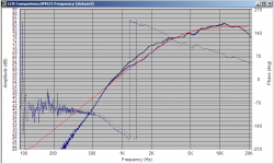
Thanks wolf, I just did a sim with the same tweeter (morel DMS37) and just a series 3.3uf cap, with and without an LCR filter. This tweeter doesn't have much of a resonant peak, but it is still obvious the difference that it creates.
Black is just with the 3.3uF cap. Blue is with LCR filter added. red is a target 4Khz 2nd order bessel rollof.
Tony.
Black is just with the 3.3uF cap. Blue is with LCR filter added. red is a target 4Khz 2nd order bessel rollof.
Tony.
Attachments
Now- think in terms of damping... The LCR with HP suppresses the impedance peak to (if done properly and compensated fully) virtually a resistive load. Being that the Fs is the most easily excited frequency of a driver and that which causes the most Xmax with the least input voltage, reducing or shorting out this frequency area damps the Fs electrically, by attenuating/shorting the voltage to the driver at this point in the audible spectra.
That all sounds very nice, but it is not exactly what happens. I've prepared a couple of sims to try and show what is actually going on. First of all, if the electrical damping of the driver changed, then it's impedance would have to change. Back in 2004 this was a topic of discussion on the Madisound board for the case of a series resistor changing the damping. My analysis showed that while the damping of the system (again note the word system, not driver) changes, the damping of the driver doesn't. Qes of the driver never changes. The impedance of the drivers is fixed.
Next, in the figures below, recognize that everything to the right of the capacitor represents some impedance load, ZL, that the capacitance sees. What happens without the LRC (which is a conjugate network) is that this load (the driver alone) has both resistive and reactive components (capacitance and inductance). The series capacitance of the 1st order crossover in combination with the inductive component of the driver's impedance at the impedance peak forms a LC resonance. You can see this in the first figure below where a cap is in series with a model of a driver's Z.
Next to it I have replace the model of the driver's Z with an inductor in series with a resistance. You can see similar behavior.
An externally hosted image should be here but it was not working when we last tested it.
In the next figure I have added a conjugate network which eliminates the the reactive components in the in the load, ZL, making it purely resistive. As you can see, there is no resonance peak in the response now because there is no inductive component in the load for the capacitor to resonate with.
An externally hosted image should be here but it was not working when we last tested it.
But the impedance of the driver model remains the same. Yes, the conjugate network has an impedance of 4.4 ohms at impedance peak of the driver model, and yes this does provide a current path to ground, but what suppresses the peak in the response curve is the elimination of the reactive nature of the load seen by the cap. This can be better observed by replacing the conjugate network with a 4.4 ohm resistor, the same value as that in the conjugate network. The last figure shows a comparison between the response with the conjugate network in red and when the shunt is just a 4.4 ohm resistor in blue. The resistor does add the same damping to the system at Fs as the conjugate network and therefore the LC resonance between the crossover cap and the inductive component of the driver's Z has a lower peak. But it is still present because the reactive components in the driver's Z have not be compensated for. (Note that the value of the series cap has been changed to compensate fro the difference impedance so as to keep the crossover point the same.)
An externally hosted image should be here but it was not working when we last tested it.
So it is not so simple as to say the LRC provides a current path to ground and therefore damps the resonance. There is more to it. Te correct conjugate network eliminates the cause of the resonance be removing the reactive components in the driver's Z around Fs. This is exactly the same as what a Zobel does to eliminate the effect of the rising impedance due to voice coil inductance. In neither case does the driver's impedance change. What changes is the impedance the upstream elements in the crossover network see, and how they interact with that impedance.
Last edited:
Hmmm......
This is using a sledgehammer to crack a walnut.
Its clear (to me at least) what the datasheet is going on about,
albeit very poorly precisely worded, and whilst JohnK's comments
are correct they are missing the point alluded to in the datasheet.
Which is the clueless don't take into account the drivers impedance
peak, and if your clueless your a lot better off including the LCR,
for the halfbaked crossover, as your clueless, you've come up with.
The problem in the explanation is reference to the impedance the
driver sees from the x/o, whist true, its glibly mentioned, and then
the following statement assumes your clever enough to work out
its not likely to be true, but implies its necessary when its true.
Which is wrong, as I and JohnK have both stated.
rgds, sreten.
- Status
- This old topic is closed. If you want to reopen this topic, contact a moderator using the "Report Post" button.
- Home
- Loudspeakers
- Multi-Way
- Qu re: Tweeter LCR resonance compensation