I'm working away on one of my first speaker rebuilds right now and am at a point of dealing with crossovers. The original speakers (stereo pair) each had two woofers and two tweeters in a vertical array. All the drivers are 16ohm but are wired in parallel so the crossover deals with an 8ohm load.
I'm planning on building new boxes for the speakers as the old ones are 1970's construction with cheap particle board and no bracing. My desire would be to separate them into one woofer and one tweeter per box, giving me four speakers in total, but my worry is that I'm not terribly well versed in crossover design just yet and would botch something up in the process. I trust where the crossover point and slope is on the original crossover, so is it possible to easily reverse engineer the current crossover while turning the loads from 8ohm to 16ohm?
I'm planning on building new boxes for the speakers as the old ones are 1970's construction with cheap particle board and no bracing. My desire would be to separate them into one woofer and one tweeter per box, giving me four speakers in total, but my worry is that I'm not terribly well versed in crossover design just yet and would botch something up in the process. I trust where the crossover point and slope is on the original crossover, so is it possible to easily reverse engineer the current crossover while turning the loads from 8ohm to 16ohm?
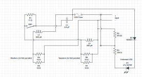
So I've finally measured and drawn up the old circuit. I just wanted to get input and fully understand what's going on here. I believe there's an L-pad in the circuit, along with a signal LED? I'd like to know what xover frequency the crossover is currently at. Also with all the extra stuff in the circuit, I'd like to keep the L-pad, not sure if the fuse is needed, but I see no point in keeping the LED. Can I drop the LED in the new crossover without adjusting anything else? Is the fuse really needed?
So with everything going on here is it as simple as doubling the inductance and halving the capacitor values?
Also, the drivers are old, but I'm not skilled enough to accurately re-measure the resistance and re-calculate everything. Any tutorials on how to do that for next time?
So with everything going on here is it as simple as doubling the inductance and halving the capacitor values?
Also, the drivers are old, but I'm not skilled enough to accurately re-measure the resistance and re-calculate everything. Any tutorials on how to do that for next time?
Attachments
Last edited:
What's the purpose of doing so ? If you need four speakers....well...make a working one.
The bobbin before the woofer should be half...more or less.
So the capacitor before the tweeter; the inductance after it...should be doubled !?
I would rework it by adding a new 8Ω tweeter only. Two tweeters are bad.
The bobbin before the woofer should be half...more or less.
So the capacitor before the tweeter; the inductance after it...should be doubled !?
I would rework it by adding a new 8Ω tweeter only. Two tweeters are bad.
Hi,
I'm not really 'into the thing' but I just swap various parts from the
garbage sack
So: you could end in doing whatever you do !
To see what happens by changing the value of the components in the crossover circuitation, see also in the 'tools' section in Strassacker: Lautsprecher - Boxen - Selbstbau, just to get the ratio ( crossover calculator)
You'll see that for the tweeter, the capacitor value diminishes as the Z rises;
and for a woofer you'll need 'less' inductance for half Z .
For the tweeter, why don't you try a modern and powerful ( 10 W) model
maybe you can try a waveguide to help it in the lower region, it also helps in making crossover easy ( sometimes ... )
As I said, it's better a single source, specially for the treble
I'm not really 'into the thing' but I just swap various parts from the
garbage sack
So: you could end in doing whatever you do !
To see what happens by changing the value of the components in the crossover circuitation, see also in the 'tools' section in Strassacker: Lautsprecher - Boxen - Selbstbau, just to get the ratio ( crossover calculator)
You'll see that for the tweeter, the capacitor value diminishes as the Z rises;
and for a woofer you'll need 'less' inductance for half Z .
For the tweeter, why don't you try a modern and powerful ( 10 W
) modelmaybe you can try a waveguide to help it in the lower region, it also helps in making crossover easy ( sometimes ...
)As I said, it's better a single source, specially for the treble
Pico, I only plan on having one tweeter per box. The diagram is of the old crossover where there were two speakers in each box. I'm looking to transfer the same crossover slopes and features to the new box.
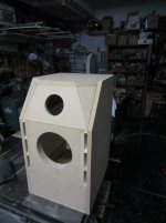
I've attached a pic of the new box so you can see there will only be one of each speaker in each box.
The online calculators really only get me so far as I'm not sure how things like the L-Pad will interact with the filters, and I'm not sure what the exact knee of the current filters are (I see that the woofer is a single order and the tweeter is a double order, but I don't know where the knee is). Really, I'm just doubling the resistance load on each channel but would like to keep the crossover the same.
Attachments
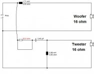
If I haven't lost my touch, the conversion is as follows. You would actually use preferred values like 3.3uF. It'll make little difference.
Regular sort of simple crossover. The bass will roll off gently and overlap with the tweeter quite a lot. Quite how well it works depends on the woofer rolling off naturally and smoothly.
Be interesting to know more about the drivers.
Regular sort of simple crossover. The bass will roll off gently and overlap with the tweeter quite a lot. Quite how well it works depends on the woofer rolling off naturally and smoothly.
Be interesting to know more about the drivers.
Attachments
Thank you very much System7, that's exactly what I wanted to have confirmed. I'll assume there should be a switch indicator on the other side of that resistor circuit.
The speakers I'm restoring are StudioLab phase inversion monitors (minitower model). The tweeters are Phillips AD0162 T15 and the woofers are some unknown model with little to no markings. Pics and discussion of the woofers can be seen at http://www.diyaudio.com/forums/multi-way/220779-can-anyone-idetify-these-8-midbass.html
I'll be sure to post pics and FR when the project is complete.
Hmm, some sort of foamed bass with damped metal dustcap. Philips dome tweeter, maybe metal with phase plate.
I'd guess the tweeter -6dB point is around 2.5kHz.
The 22 ohm resistor will be your level/brightness adjustment.
I'm not quite clear how the twin tweeters are installed in the original. The pictures I saw were an MTM (D'Appolito) alignment with single tweeter. That's not a difficult conversion either.
The originals looked almost identical to this:
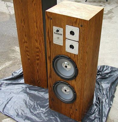
But the fuse and L-Pad switch were on the rear and the two tweeters were centered on the baffle.
Edit: Found a pic of the exact model:
But the fuse and L-Pad switch were on the rear and the two tweeters were centered on the baffle.
Edit: Found a pic of the exact model:
An externally hosted image should be here but it was not working when we last tested it.
Last edited:
Yup, I think I start to get it.
The LED indicator just draws a little bit of power off the amplifier output and glows at high levels. The "L-pad" is actually just a variable resistor.
Metal dustcaps aren't totally unknown even now, but you can notch their worst breakup at high frequency. Might be possible to do something more sophisticated with the woofer filter too.
Just have to see how it goes really. Why do we spend time on these old speakers? Fun, I guess.
system7 I notice that you've specified the resistance values of the inductors on that schematic. How dead on do the actual values need to be there? I'm looking into prices and see that thinner wire inductors cost less but have higher resistance. What is the result in the audio, lower volume level?
You usually use a ferrite-core (on the right here) on bass units, and an air-core (on the left) on treble. One of my efforts.
Ferrite cores can get lowish resistance at high values around 2mH. The effect of an ohm or so is hardly noticeable in practise. But it is generally felt that tweeters don't like a high resistance coil. Lets through some undesireable low frequencies leading to IM distortion.
FWIW, I think you might try 5uF or so shunt capacitance across the woofer. Should roll it off a bit faster.
An externally hosted image should be here but it was not working when we last tested it.
Ferrite cores can get lowish resistance at high values around 2mH. The effect of an ohm or so is hardly noticeable in practise. But it is generally felt that tweeters don't like a high resistance coil. Lets through some undesireable low frequencies leading to IM distortion.
FWIW, I think you might try 5uF or so shunt capacitance across the woofer. Should roll it off a bit faster.
Most folks use polypropylene types. 630V jobbies are pricier and bigger than 250V types. My own experience is the 630V types sound a bit brighter on treble filters. Not much in it really.
Wirewound resistors come in 3, 7 and 10W and you can increase power handling by pairing them up. 10W can be a physically large, but the theory is they are less susceptable to change of resistance with heating. I tend to overspecify to avoid fires! On the other hand, 3W jobbies can act as a fuse!
Oh, BTW, you can still use leaded solder for personal use, much easier stuff to apply than the ghastly lead-free that our Masters in Brussels (Who know better than us what is good for us... LOL) have decreed for the industry.
Last edited:
ferrite cores are fine, although for larger values I use larger diameter cores. There is a technical reason which currently escapes me!
Saturation? Its a good reason nevertheless.
E.g. I have 2.2mH in two core diameters; 15mm and 40mm. The larger are far better, higher current rating, and lower DCR.
The smaller cores are easy to get into distortion (in a 3rd or 4th order low pass) by just the addition of another series L component.
I use 7W resistors and have never required higher wattage types, but thats just my experience. Standard polys or polyester are fine
Last edited:
- Status
- This old topic is closed. If you want to reopen this topic, contact a moderator using the "Report Post" button.
- Home
- Loudspeakers
- Multi-Way
- Crossover adjustment/re-engineering