Hi all,
I bought a DIY 2 way speaker system using Vifa drivers and the crossover network puzzles me. The system sounds fairly balanced and smooth so it seems to work.
Anyway here is the schematic, I couldn't read the value of the bottom inductor but it is definitely between 1mH and 1.8mH.
Main questions are:
-Is this some sort of series crossover?
-Looks like a 1st order HP? Or is there something in the path back through the woofer?
-Dual inductors on the woofer? Bass enhancement maybe?
Please help, I wan't to know what they were thinking.")
Thanks.
I bought a DIY 2 way speaker system using Vifa drivers and the crossover network puzzles me. The system sounds fairly balanced and smooth so it seems to work.
Anyway here is the schematic, I couldn't read the value of the bottom inductor but it is definitely between 1mH and 1.8mH.
Main questions are:
-Is this some sort of series crossover?
-Looks like a 1st order HP? Or is there something in the path back through the woofer?
-Dual inductors on the woofer? Bass enhancement maybe?
Please help, I wan't to know what they were thinking.
Thanks.
Attachments
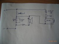
I am no expert, but it looks like a second order Series crossover.
The First order is 5.5Uf across the Woofer and .56 H across the tweeter.
The other Cap in series with the tweeter gives the second order roll off.
Ditto for the Other Inductor.
I know that series crossovers model in Soundeasy (I have done it),
The Series crossover in the Modula MT drove my brother crazy.
If it works, so much the better.
HTH
Doug
The circuit of the xover is for a second order series layout as DougL says,however the component values do not appear to correspond to text book values.Perhaps knowing the speaker impedances would provide more clues.
Yes, yes, yes. The combined result is the acoustic response (drivers , placement, and baffle) added to the electrical network that includes the driver model ( far more than the inductance, D'Appolito has a decent model). A book crossover is just a place to start. It will never be optimum.
So what is the advantage (if any) of using a series x-over over a conventional parallel type one?
I don't know that it is an advantage. Some designers swear by them, but it's really only another means to an end, or another way to skin a cat.
Later,
Wolf
For passive circuits,a parallel second order crossover is a better choice if the issues of phase and signal summation are not a priority.The reason for this is that the high frequency driver receives some damping via the falling impedance of the parallel connected inductor in the crossover region and below.This does not happen with a parallel first order (or the // third order).I would agree with tvrgeek that a text book design is just a starting point and that the acoustic response and measurements are required for a proficient design.
re:"what is the advantage (if any) of using a series x-over over a conventional parallel type one?" - for 2nd order,none: Series vs. Parallel Crossover Networks
For passive circuits,a parallel second order crossover is a better choice if the issues of phase and signal summation are not a priority.The reason for this is that the high frequency driver receives some damping via the falling impedance of the parallel connected inductor in the crossover region and below.
IMO this is only marginally helpful if the resonance frequency of the high frequency driver is fairly close to the cross-over frequency. Electrical damping is relevant only in the band of frequencies close to the resonant frequency of the driver. At frequencies well above resonance, the driver is mass controlled.
Best Regards,
Pete
Hi,Pete,I have always followed guidelines when choosing a crossover point for a tweeter and I certainly would not contemplate trying to use a tweeter with a resonance close to that frequency.Generally with dome tweeters,I look for the area where the impedance is at its lowest and the phase zero.This is typically around 3 kHz for 25 mm domes.The excursion is part of the consideration in the xover selection,particularly at high SPL's,because as you attempt to go lower a greater movement of the diaphragm occurs ( ka point).For a 12 dB/octave network this means that the resonance should be chosen to be less than 1.5 kHz.Things are tougher for first order xovers and a more robust tweeter with an Fs of 750 Hz should be used.In this latter case a quasi 2nd order( a modified 1st order series network) is a good choice and it does benefit from a tweeter offset to correct its' lobing pattern. For compression drivers (horns) crossover choice is far more difficult as the(L.F.!) resonance is often close to the desired point and the impedance and phase can fluctuate a great deal.
VaNarn,
I certainly agree with everything that you say in your post #12. In my previous post, I wasn't suggesting that the resonance and crossover frequencies of a driver should be close together, I do understand that that should be avoided whenever possible. My post was meant to address the conventional understanding (misunderstanding IMO) that electrical damping of the driver is important throughout the operating frequency range of the driver, including in the range that is greater than about 3 times the resonance frequency of the driver. This is supposedly one of the evils of passive crossover networks that active crossing over "cures" effecting an amazing (subjective) improvement in reproduction. -Not that I don't see advantages to active.
Regards,
Pete
- Status
- This old topic is closed. If you want to reopen this topic, contact a moderator using the "Report Post" button.
- Home
- Loudspeakers
- Multi-Way
- Crossover design questions