I'm just finishing a nice big sub, and these last few days while everyone here has had flu, instead of finishing it off I've been inside looking after them, and thought I'd use the time to see if I could work out how to build some reasonably cheap two way speakers to work as rear speakers in a 5.1 setup.
The room is 10 m by 3.2 m and the TV and sofa face each other in the middle across the short distance. The rear speakers will need to go on the walls behind the sofa and 2.5 m away on each side. I may end up pointing them out into the room not straight back along the walls. I'm going to stick to conventional shapes for ease of assembly, as I'm limited in working space (it's the kitchen or the garden patio basically) although I could well go for a massive radius on the edges (2" or 5 cm in metric), as I just really like the look of rounded edges on speakers.
The requirements for the speaker are simple, in that there will always be a sub on whenever the rear channels are called on, so the lower limit for flat response can be set at 100 Hz. This means they can be sealed, and the second requirement will be that they should be small. Finally, I don't want the total cost to go over £200 for the pair (I mean, not by much anyway") ).
).
In trying to learn about designing speakers I found this page about a design contest using set drive units very useful and one of the first things I did was to get the download the Passive Crossover Designer spreadsheet, downloaded the provided data files for the drive units and reproduced the competition entries. I'm in the UK however, and can't find a supplier for the ZA14W08 drive unit, otherwise I might have been tempted to build one of these designs. However, I can easily get the tweeter used, the SB Acoustics SB29RDCN-C000-4.
So, I looked to see what drive units I could find to do something similar to the designs above and from reading the test of the Seas U16RCYP at Zaph|Audio I thought I may as well use this as a starting point, and it's not too expensive from here. After playing about, I looked at how much I was reducing the tweeter output to match the woofer, and replaced the 1.2" 94 dB sensitivity SB Acoustics SB29RDCN-C000-4 with the 1" SB26STC-C000-4 which is still 91.5 dB sensitivity and only just over half the price, and seems to be well regarded.
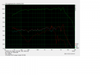
So, with these two selected as a first go, I traced the frequency response curves and impedance curves (here) and had a go at making a crossover which was fairly flat. So, the crossover for the woofer is third order with the values for the elements as
L2 mH 1.8 (with resistance assumed to be 0.20 Ohms)
C2 uF 15.00
L3 mH 0.80 (with resistance assumed to be 0.20 Ohms)
a parallel RC pair with values
C uF R Ohm
10.00 10.00
and for the tweeter a fourth order crossover with values
C9 uF 15.00
L9 mH 0.2 (with resistance assumed to be 0.20 Ohms)
C10 uF 25.00
L10 mH 1.00 (with resistance assumed to be 0.20 Ohms)
and a 2 Ohm resitor in series and a 2.5 Ohm resistor in parallel after the other elements.
So, I need to work out a layout for the drivers in a cabinet, which will most likely be 7 litres in volume, from a short play with WinISD earlier. Then I can look and see how the off axis response will work.
Anyway, I'm just kicking this about on a spreadsheet right now, so if anyone can suggest how to improve these, please do. I've looked at the overall response, which seems to be lean and might be bright on axis, but then, these might not end up being listened to on axis much, so I won't worry until I have figured out how to lay out the drivers.
Please note I found an error in the impedance file I generated for the tweeter when I first posted this, which has been corrected. Sorry!
The room is 10 m by 3.2 m and the TV and sofa face each other in the middle across the short distance. The rear speakers will need to go on the walls behind the sofa and 2.5 m away on each side. I may end up pointing them out into the room not straight back along the walls. I'm going to stick to conventional shapes for ease of assembly, as I'm limited in working space (it's the kitchen or the garden patio basically) although I could well go for a massive radius on the edges (2" or 5 cm in metric), as I just really like the look of rounded edges on speakers.
The requirements for the speaker are simple, in that there will always be a sub on whenever the rear channels are called on, so the lower limit for flat response can be set at 100 Hz. This means they can be sealed, and the second requirement will be that they should be small. Finally, I don't want the total cost to go over £200 for the pair (I mean, not by much anyway
). In trying to learn about designing speakers I found this page about a design contest using set drive units very useful and one of the first things I did was to get the download the Passive Crossover Designer spreadsheet, downloaded the provided data files for the drive units and reproduced the competition entries. I'm in the UK however, and can't find a supplier for the ZA14W08 drive unit, otherwise I might have been tempted to build one of these designs. However, I can easily get the tweeter used, the SB Acoustics SB29RDCN-C000-4.
So, I looked to see what drive units I could find to do something similar to the designs above and from reading the test of the Seas U16RCYP at Zaph|Audio I thought I may as well use this as a starting point, and it's not too expensive from here. After playing about, I looked at how much I was reducing the tweeter output to match the woofer, and replaced the 1.2" 94 dB sensitivity SB Acoustics SB29RDCN-C000-4 with the 1" SB26STC-C000-4 which is still 91.5 dB sensitivity and only just over half the price, and seems to be well regarded.
So, with these two selected as a first go, I traced the frequency response curves and impedance curves (here) and had a go at making a crossover which was fairly flat. So, the crossover for the woofer is third order with the values for the elements as
L2 mH 1.8 (with resistance assumed to be 0.20 Ohms)
C2 uF 15.00
L3 mH 0.80 (with resistance assumed to be 0.20 Ohms)
a parallel RC pair with values
C uF R Ohm
10.00 10.00
and for the tweeter a fourth order crossover with values
C9 uF 15.00
L9 mH 0.2 (with resistance assumed to be 0.20 Ohms)
C10 uF 25.00
L10 mH 1.00 (with resistance assumed to be 0.20 Ohms)
and a 2 Ohm resitor in series and a 2.5 Ohm resistor in parallel after the other elements.
An externally hosted image should be here but it was not working when we last tested it.
An externally hosted image should be here but it was not working when we last tested it.
An externally hosted image should be here but it was not working when we last tested it.
An externally hosted image should be here but it was not working when we last tested it.
An externally hosted image should be here but it was not working when we last tested it.
So, I need to work out a layout for the drivers in a cabinet, which will most likely be 7 litres in volume, from a short play with WinISD earlier. Then I can look and see how the off axis response will work.
Anyway, I'm just kicking this about on a spreadsheet right now, so if anyone can suggest how to improve these, please do. I've looked at the overall response, which seems to be lean and might be bright on axis, but then, these might not end up being listened to on axis much, so I won't worry until I have figured out how to lay out the drivers.
Please note I found an error in the impedance file I generated for the tweeter when I first posted this, which has been corrected. Sorry!
Last edited:
I have just modelled these without looking at room effects, so that's next on the list to do, as soon as I have time.
The fronts are Monitor 9's (20 year old 2 way) which I recently changed to biamped (see here). It was looking help on that which was how I first found out about the DIY audio scene. They have a 6.5" coated paper cone, metal dome tweeter and cross at 6 kHz. They may be next on the list to replace (or perhaps just put new drivers in) but I want to try building the rears first to get some experience!
The fronts are Monitor 9's (20 year old 2 way) which I recently changed to biamped (see here). It was looking help on that which was how I first found out about the DIY audio scene. They have a 6.5" coated paper cone, metal dome tweeter and cross at 6 kHz. They may be next on the list to replace (or perhaps just put new drivers in) but I want to try building the rears first to get some experience!
Anyway, I'm just kicking this about on a spreadsheet right now, so if anyone can suggest how to improve these, please do.
Hi,
I checked your crossover design and think it's basically well done, congratulations! Thus I can not say how to improve it, but probably it could be simplified. My usual approach is to start with a 2nd order crossover and to increase the order of a filter only if there is a reason to do that. Crossover parts are expensive and it's always worth to keep the number of components as low as possible. For example, a 4th order high-pass filter for the tweeter is rather unconventional, you can omit the large 1mH coil for sure.
You know it may not even be necessary to do a 2-Way. Most people ( Not us ) are happy with a small 3 inch full range in a small cube, why not think about putting a good 4 or 5 inch full range in a proper box or even a reasonably sized sealed box as a starter project and use the experience gained and the money saved to put towards new front L&Rs using the same full range as the mid
For best sounding HT all the speakers should have the same tonality so making a new centre would also be a good idea
For best sounding HT all the speakers should have the same tonality so making a new centre would also be a good idea
My usual approach is to start with a 2nd order crossover and to increase the order of a filter only if there is a reason to do that. Crossover parts are expensive and it's always worth to keep the number of components as low as possible.
Don't forget also that tolerance of the components of a filter greater than 2nd order must be tighter than for 2nd order if the higher order filter is to perform according to design. Sorry, I don't have the experience to say exactly what tolerance is required for designs greater than 2nd order. I would imagine also any non-ideal impedance variations of the connected-to driver will result in a more severe change in frequency response.
Regards,
Pete
Hi,
I checked your crossover design and think it's basically well done, congratulations! Thus I can not say how to improve it, but probably it could be simplified. My usual approach is to start with a 2nd order crossover and to increase the order of a filter only if there is a reason to do that. Crossover parts are expensive and it's always worth to keep the number of components as low as possible. For example, a 4th order high-pass filter for the tweeter is rather unconventional, you can omit the large 1mH coil for sure.
Thanks, you're dead right about the large coil, here is the crossover set to third order, by deleting just that bit and keeping the rest.
An externally hosted image should be here but it was not working when we last tested it.
I might struggle to get the phase to agree at crossover if I go to second order on the tweeter, I'll try it though, but this works fine.
Thanks!
You know it may not even be necessary to do a 2-Way. Most people ( Not us ) are happy with a small 3 inch full range in a small cube, why not think about putting a good 4 or 5 inch full range in a proper box or even a reasonably sized sealed box as a starter project and use the experience gained and the money saved to put towards new front L&Rs using the same full range as the mid
For best sounding HT all the speakers should have the same tonality so making a new centre would also be a good idea
Thanks for the suggestion. I've seen some small 3" drivers that looked fun, but all the larger ones I've ever seen look a bit uneven. Are there any particularly good ones to look at?
Dave is the single driver expert, look at any of planet 10s recommendations but I imagine any of the Fostex would do
Hard to give a recommendation from the other side of the planet, I have never been happy with a stand alone 3 inch ( great top ends lousy bass ) and surrounds seem to do a little better without the treble- this is why the use of dual side firing tweeters in many designs.
I use mine firing up towards the ceiling for instance
Right, I've had another look at the cabinet size and how to lay things out.
The Seas U16RCY/P will give a maximally flat response in a 6.5 litre cabinet, and as I'm not looking for them to do much below 100 Hz, that suits me fine. The cabinet I'm thinking of is 176 x 221 x 306 mm on the outside, in 18 mm mdf (as then I can round the corners a lot) with 0.5 litres allowed for the crossover and bracing. The drivers have diameters of 146 mm and 100 mm, so there is 20 mm below the woofer to the dge, 10 mm between the drivers and 20 mm above the tweeter to the top. There is 15 mm either side of the woofer on the outside, but it does not hit the walls as the internal diameter is only 126 mm.
I looked for information on the directivity of the woofer and found this very helpful post http://www.diyaudio.com/forums/mult...restigious-two-monitor-dxt-3.html#post3062461 about some measurements done by Gornir who runs the www.audioexcite.com web site, and who has used these woofers for a bass reflex design. From these measurements it seems the U16RCY/P is essentially omnidirectional up to 2 kHz, and as I'm planning to have a steep crossover at 1.8 kHz there should really be no issues with dispersion until the frequencies get up to where the tweeter is becoming directional, but then that will be so high I don't really care for rear speakers. This may be slightly compensated by the rise at above 10 kHz from this tweeter. I have even read that the treble response for rear speakers should drop off, as sound from further away normally exhibits a diminshed treble response. Oh well, I'll have fun trying to see if I can hear a difference if I point them in different angle across the room. I do like the idea though, that through the midrange these should not be at all directional, so I hope they will work well as rear speakers.
Anyway, I've done some reading about the benefits and drawbacks of putting the tweeter on the centre axis with the woofer, or off nearer one side and have read some opinions that on axis is less good for the on axis response but better for the off axis response. If this is true, I'll obviously keep the tweeter centred for these. I have not found any pages with measurements to back this up though, so I'd be grateful if anyone could point me to a source which might back this up.
One final thing I would like to do is to simulate the vertical response, but I do not know where to get measurements for the offset back or forward from the baffle of the acoustic centre of the drivers, is this easily measurable, and does it relate to the actual surface of the cone?
Best Wishes,
Nick.
An externally hosted image should be here but it was not working when we last tested it.
The Seas U16RCY/P will give a maximally flat response in a 6.5 litre cabinet, and as I'm not looking for them to do much below 100 Hz, that suits me fine. The cabinet I'm thinking of is 176 x 221 x 306 mm on the outside, in 18 mm mdf (as then I can round the corners a lot) with 0.5 litres allowed for the crossover and bracing. The drivers have diameters of 146 mm and 100 mm, so there is 20 mm below the woofer to the dge, 10 mm between the drivers and 20 mm above the tweeter to the top. There is 15 mm either side of the woofer on the outside, but it does not hit the walls as the internal diameter is only 126 mm.
I looked for information on the directivity of the woofer and found this very helpful post http://www.diyaudio.com/forums/mult...restigious-two-monitor-dxt-3.html#post3062461 about some measurements done by Gornir who runs the www.audioexcite.com web site, and who has used these woofers for a bass reflex design. From these measurements it seems the U16RCY/P is essentially omnidirectional up to 2 kHz, and as I'm planning to have a steep crossover at 1.8 kHz there should really be no issues with dispersion until the frequencies get up to where the tweeter is becoming directional, but then that will be so high I don't really care for rear speakers. This may be slightly compensated by the rise at above 10 kHz from this tweeter. I have even read that the treble response for rear speakers should drop off, as sound from further away normally exhibits a diminshed treble response. Oh well, I'll have fun trying to see if I can hear a difference if I point them in different angle across the room. I do like the idea though, that through the midrange these should not be at all directional, so I hope they will work well as rear speakers.
Anyway, I've done some reading about the benefits and drawbacks of putting the tweeter on the centre axis with the woofer, or off nearer one side and have read some opinions that on axis is less good for the on axis response but better for the off axis response. If this is true, I'll obviously keep the tweeter centred for these. I have not found any pages with measurements to back this up though, so I'd be grateful if anyone could point me to a source which might back this up.
One final thing I would like to do is to simulate the vertical response, but I do not know where to get measurements for the offset back or forward from the baffle of the acoustic centre of the drivers, is this easily measurable, and does it relate to the actual surface of the cone?
Best Wishes,
Nick.
Last edited:
For best sounding HT all the speakers should have the same tonality so making a new centre would also be a good idea
This statement should be repeated over and over and over and over again.
The requirements for the speaker are simple, in that there will always be a sub on whenever the rear channels are called on, so the lower limit for flat response can be set at 100 Hz. This means they can be sealed, and the second requirement will be that they should be small. Finally, I don't want the total cost to go over £200 for the pair (I mean, not by much anyway
I just finished designing an HT sat using a Visaton W130S 8 Ohm woofer and either a Vifa BC25SC06 or Vifa XT25SC09 dual ring radiator tweet. I've listened to it with the BC tweet and it's a good match although it requires a lot of padding to match the woof. Just getting started on measuring and tweaking the crossover for the XT25 dual ring. Without any baffle step correction f3 is about 81Hz. Parts list below, all parts are available at Parts Express. The cab can be either a "Knock Down" .23 cu ft or a finished .25 cu ft but that will drive the cost up to over $100 per unit. The unfinished cabs are easy to seal and paint and will weigh about 12 lbs including drivers when finished. The Vifa XT tweeter is slightly more expensive. I don't have the crossover finished yet but will within 10 days or so. It's basically a standard Quasi-forth order asymmetric LR crossover (credits to Jeff B.). Tweet has third order slope and woofer has second order slope to get phase to align. If you want an even cleaner midrange we can add a crunch filter to kill the breakup mode this woofer has at about 6K but it will reduce efficiency to below 85db 1w/1m and change the crossover a little. The woofer has two peaks, a small peak at 4K and another peak at 6K. I don't think the first resonance is a breakup mode. It does not show an increase in distortion at that peak but I could be wrong. Regardless it sounds very good having an especially good sounding bottom end for such a small woof. The Vifa BC25SC06 is a well known, well documented tweeter used in many projects and kits. The Visaton woofer is a little newer. Haven't see too many uses for it yet... But it's low cost and decent response make it a target for future projects.
Cabinet 24.90 (PE .23 knock down)
Woofer 24.12 (Visaton W130S 8 Ohm)
Tweeter 17.25 (Vifa BC25SC06)
Cup 5.50 (PE Wire cup 3 7/8" with spring clips)
Cap 1.70 (Not finalized yet)
Cap 2.60
Cap 4.33
Coil 4.21
Coil 6.69
Wire 3.00
Screws 2.00
Crossover board 5.70
=================
$100.00
This is NOT a kit, just a parts list and a crossover diagram. You have to mount, solder up then mount the crossover, cut openings in the baffle (2" and 4 1/4" hole saws work fine) and glue the cab together. But it's a good quality HT sat that fits your bill. Flyer PDF is attached. Also see attached distortion sweep. I might have been wrong, there is a small distortion peak at 4K but it's very small.
Attachments
Last edited:
Looking at what you've done in previous posts you could probably design the crossover yourself given the raw data. I do have raw sweeps but I was having trouble getting phase to align and I suspect my measurements are off or I forgot something. I think I need to go back and take better measurements using ARTA and converting to minimum phase. That and my test baffle indicates I need to move the drivers so I'm waiting till Tues or Wed to get over the the shop and cut the baffle off this box so I can remount them. I really like the PE knock-down boxes, they are very well made and make it very easy to make a decent quality finished speaker. They are also very inexpensive if you purchase enough stuff and get free shipping.
For best sounding HT all the speakers should have the same tonality so making a new centre would also be a good idea
This statement should be repeated over and over and over and over again.
I totally agree. I'm starting to wonder if I pick the right tweeter and midwoofer, could I make some two way TMs or dipoles for rear speakers, an MTM for the centre with the tweeter off centre and the phase adjusted to make it fire up slightly to aim at ear level at 2.5 metres, and either some TMMs or three ways using the tweeter and mid unit for main left and right speakers. I'll have to pick the right time to explain this brilliant concept to my wife.
I'm aiming to build the rear speakers first as I don't have any at the moment, and that way I can try them out in place of the front speakers and see if I still like the idea of using the same drive units.
I just finished designing an HT sat using a Visaton W130S 8 Ohm woofer and either a Vifa BC25SC06 or Vifa XT25SC09 dual ring radiator tweet.
Thanks! I can get this woofer from Conrad Electronic UK. I'll have to make my own enclosures though, I've looked for the Dayton kits before and they do not seem to be distributed over here (UK). Shipping things over is usually very expensive, if you want to be sure they'll arrive.
Is the crossover diagram in the pdf file? I could see the image of the driver and the title text.
Please let me know how you get on with this one, thanks.
Shipping things over is usually very expensive, if you want to be sure they'll arrive.
If the value of the item shipped from the USA is over £20 you not only have to account for shipping costs but also for customs&excise duty and VAT.
That alone usually doubles the cost even without shipping costs.
The phase you have posted looks like electrical phase and not actual driver phase. Have you measured the phase or extracted minimum phase from your frd files? If not, you need to start over. Sorry.
Thanks for pointing that out. I've used the Response Modeller to do this, and it did make a difference. I also modelled the box effects, and this has dropped the bass a fair bit once the baffle step comes in. To compensate for the change, the L3 inductor in the crossover has changed to 0.55 mH from 0.8 mH.
An externally hosted image should be here but it was not working when we last tested it.
I don't think this is satisfactory any more, so I think it must be back to the drawing board.
Thanks for taking my advice and not misunderstanding it as a put down. I get that often it seems. And I'm glad a major problem was solved before expensive parts were purchased.
Also remember that using response modeler gives minimum phase. You'll need to enter the driver x, y, z coordinates if you're not measuring the drivers. For z, you'll just have to take a stab in the dark. I suggest -0.025 for the woofer and 0 for the tweeter. You won't be far enough off that it matters. You are, after all, using them as surrounds. So you'll likely rarely be on axis vertically.
Good luck
- Status
- This old topic is closed. If you want to reopen this topic, contact a moderator using the "Report Post" button.
- Home
- Loudspeakers
- Multi-Way
- Design for a cheap two way for use as rear speakers in 5.1 setup