Yea, right on target. Slopes are right where I want them, for the most part.DrNick - RE Post 31.
That looks great. Nice cross over point.
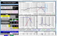
Not really, the woofer has a 2 db hump where it begins to roll that needs to be ironed out. Probably needs a little more inductor and a little less cap or just more inductor. Probably going up to 1.5 or 1.7 on the inductor and maybe a little adjustment on the cap will take care of it. The slope is too steep though, I don't know why I was modeling an LR4 on the woof.Good driver integration. Very flat response.
Yea, it's actually very simple. I have an LR4 slope on both drivers with only 4 components. I think I'll need to reduce the woofer slope to get the phase where I ultimately want it. Symmetric crossovers never work on a flat baffle. They often work with LR4 on tweet and Butterworth second or Butterworth third on woofer, depending... It will fit though, no doubt about it and probably with only 4 components and an L-Pad.Relatively simple cross over.
Look at impedance though. I should have displayed electric phase too to see if there were any high angles. Amps don't like low impedance with large phase angle. The impedance itself isn't as big a deal as the phase when the impedance is low like that. I need to find a different set of L-Pad resistors to pad down the tweet. It's modeled using like a series 2.5 and a parallel 1.4 or something stupid like that. The issue is that with different resistors the phase changes too so it's a "gotcha" situation that could have been avoided if I'd chosen an 8 Ohm tweet. But there are always -alternatives-. And no you can't just do with a series before the crossover, it messes with the fs of the tweeter just like it would with a woofer. With the fs close to crossover like this is with large resistor values it will raise the Q and create a peak in the response. A proper L-Pad pads the tweet while maintaining the correct source impedance for the crossover that's behind it. Impedance is a two way street...
 ... And it's not purely resistive...
Last edited:
Woops, thought you were talking to me...DrNick - RE Post 31.
That looks great. Nice cross over point.

DrNick - RE Post 31.
That looks great. Nice cross over point. Good driver integration. Very flat response. Relatively simple cross over. Just to be clear though, you did enter driver offsets? Woofer z should be something like -0.025 if using the newer version of PCD. The older version should be 25.0 or something iirc.
This shouldn't make a terrible difference, it's probably fine.
There's always one more thing. I had mentioned this in a previous post and then forgotten. So, here is version 4, with the woofer at -25 mm in z.
An externally hosted image should be here but it was not working when we last tested it.
and with the tweeter reversed
An externally hosted image should be here but it was not working when we last tested it.
This is using this session file, and frd and zma files.
http://www.drnicholas.plus.com/Satellite/Satellite%204th%20with%20offset.csp
http://www.drnicholas.plus.com/Satellites/SB Acoustics SB26STC-C000-4 miniphase.frd
http://www.drnicholas.plus.com/Satellites/SB Acoustics SB26STC-C000-4 miniphase.zma
http://www.drnicholas.plus.com/Satellites/Seas H1520-08 U16RCYP modified transformed.frd
http://www.drnicholas.plus.com/Satellites/Seas H1520-08 U16RCYP box impedance model modified.zma
The new crossover has only one inductor, so it is now third order electrically. As there is only one, I've changed it to have a lower resistance.
L2 2.00 mH, 0.1 Ohms
C2 12.00 uF
With a parallel leg over the woofer containing C 20 uF and R 20 Ohms. Before C2 was 15 uF, we had another inductor and only a 10 Ohm resistor in the parallel leg, so not a huge change, just enough to get the phase back in line.
The tweeter is crossover is unchanged from before, and has a third order section
C9 15 uF
L9 0.2 mH 0.2 Ohms
C10 25 uF
with a series resistor 2 Ohm after the crossover, and parallel resistor over the tweeter of 2.5 Ohms.
Thanks for reminding me of this! I'm hoping this thread will be insturctive, as everyone else can learn from each mistake I make.
Last edited:
Are you thinking of this pair up as a possibility? Can you get these drivers at decent prices?
I'm probably going to model a larger 6" or a metal cone 5.5" driver next, just to see what difference I can find from going up one size or a little in price, and to think what I might end up using for the main front speakers. I like the idea of the Seas U16RCY unit, as it fits in the same size cutout as most 5" drivers (12.6 cm), but has a larger piston area (99 cm2) than most, so the bass in a sealed box is better, so anything else will have to have more in the bass than this one, or fit in an even smaller box.
I've started modelling things in WinISD to check box sizes and the bass end. I looked at the CA18RLY 6.5" driver, but it needs 28 lires in a sealed box, so I might just try some other models.
All the best,
Nick.
Last edited:
SIGGMA-VV51-HT
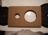
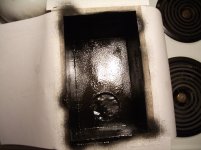
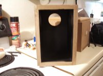
Anyway, DrNick, here is the enclosure for the Visaton HT Sat along with speaker board before gluing it in place. I sprayed the interior with Quiet Kote to reduce any panel ringing and chamfered the interior of the woofer mount to reduce any compression that might occur. Tweet and woof will be surface mounted and I'll just have to live with any peaks and dips for now. I'll glue them up tonight and be ready for measurements in the morning. I'm also going to spray the back of the baffle before I glue them up. I'll get a pic if I can.
The official name of this is the SIGGMA-VV51-HT. SIGGMA (me) VV51 is Visaton 5" Vifa 1", HT.")
Anyway, DrNick, here is the enclosure for the Visaton HT Sat along with speaker board before gluing it in place. I sprayed the interior with Quiet Kote to reduce any panel ringing and chamfered the interior of the woofer mount to reduce any compression that might occur. Tweet and woof will be surface mounted and I'll just have to live with any peaks and dips for now. I'll glue them up tonight and be ready for measurements in the morning. I'm also going to spray the back of the baffle before I glue them up. I'll get a pic if I can.
The official name of this is the SIGGMA-VV51-HT. SIGGMA (me) VV51 is Visaton 5" Vifa 1", HT.
Attachments
Last edited:
Forgot one picture. I added 1/2" round over on all baffle sides on front to reduce diffraction.
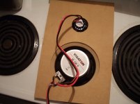
BTW, that Quiet Kote work GREAT. It sounds dead even banging on the outside. I might not even need any stuffing in the box. It will be even better once I get the box glued up. You can see my temporary cardboard crossover in the background...
BTW, that Quiet Kote work GREAT. It sounds dead even banging on the outside. I might not even need any stuffing in the box. It will be even better once I get the box glued up. You can see my temporary cardboard crossover in the background...
Attachments
Last edited:
I'm probably going to model a larger 6" or a metal cone 5.5" driver next,
You might check out the Visaton AL-130 Aluminum cone driver. It probably fits your specifications. It's a tad more expensive but has been successfully used in several projects. Paired with one of the less expensive Vifa tweets if I recall correctly, so there is a crossover designed for it somewhere. Yea, here's a goo link: http://www.diyaudio.com/forums/multi-way/214989-tqwt-visaton-al130-g20sc-finished.html
Anyway, DrNick, here is the enclosure for the Visaton HT Sat along with speaker board before gluing it in place. I sprayed the interior with Quiet Kote to reduce any panel ringing and chamfered the interior of the woofer mount to reduce any compression that might occur. Tweet and woof will be surface mounted and I'll just have to live with any peaks and dips for now. I'll glue them up tonight and be ready for measurements in the morning. I'm also going to spray the back of the baffle before I glue them up. I'll get a pic if I can.
The official name of this is the SIGGMA-VV51-HT. SIGGMA (me) VV51 is Visaton 5" Vifa 1", HT.
Cool, love the rounded baffle! I really appreciate seeing these, as I am going to have to wait till Next month at the earliest to go shopping for hi-fi again, so it may be a while before I can get going on whatever I end up making.
One thing I'm pondering is that the drivers that appear to work best in small enclosures when you model them in WinISD are often those intended for vented cabinets, but is this really true? As an example, the Seas CA18RLY is designed to work best sealed, and appears to give a flat response in 28 litres. The CA18 RNX, with the same cone (or very close) but a beefier magnet, gives less bass when sealed, but models with a flat response in 8 litres. The U16RCY that I'm looking at also appears to be a bigger magnet design that most people would be using in a bass reflex design. is there any problem going sealed with drivers like this?
Cheers,
Nick.
Cool, love the rounded baffle! I really appreciate seeing these, as I am going to have to wait till Next month at the earliest to go shopping for hi-fi again, so it may be a while before I can get going on whatever I end up making.
That might be better for you since it will give you a chance to "due diligence".
The drivers you reference will have a different Qts. One will be higher (vented) and the other will be lower (sealed).One thing I'm pondering is that the drivers that appear to work best in small enclosures when you model them in WinISD are often those intended for vented cabinets, but is this really true? As an example, the Seas CA18RLY is designed to work best sealed, and appears to give a flat response in 28 litres. The CA18 RNX, with the same cone (or very close) but a beefier magnet, gives less bass when sealed, but models with a flat response in 8 litres. The U16RCY that I'm looking at also appears to be a bigger magnet design that most people would be using in a bass reflex design. is there any problem going sealed with drivers like this?
Cheers,
Nick.
As for the question; No, many drivers will model for either sealed or vented but a sealed design might require too large an enclosure or a ported might require too low a tuning for a particular enclosure size, like the port is too long or the box is too big etc. Generally speaking high Qt (.4 and up) speakers go in vented enclosures and low Qt do best in sealed but that's a very general rule. Most of us wouldn't be using a high Qts driver in an enclosure. Usually those with a Qt over .6 are intended for open baffles. If the drivers Qt is high a small enclosure will raise the fc, and usually f3 as well, too much, unless you want or like a finished Qts over .7. What they are giving you (the colored slider thing) is the EPB (efficiency bandwidth product) which is a calculation that includes the Q and fs and maybe something else. It's a better predictor of enclosure use. But just because a driver has a high EPB doesn't mean you can't or shouldn't use it in a sealed enclosure. You can put any cone driver in either type of enclosure and get useful results with the exception of horn drivers which are specially made for horns and contact transducers (bass shakers) and other exotic transducers.
Last edited:
SIGGMA-VV51-HT update.
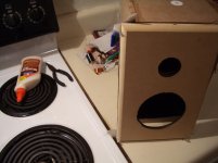
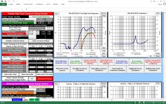
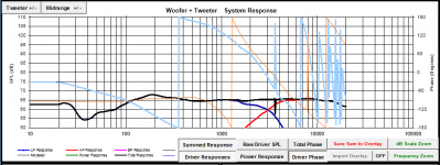
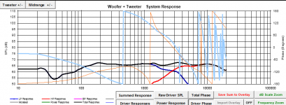
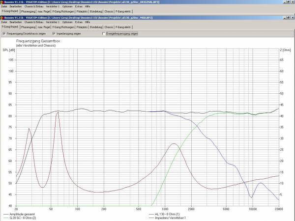
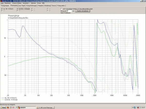
I glued up the boxes and took a measurement this morning. Not good. I'm seeing a 5 db peak in tweeter response around 1.5K that's either from baffle edge diffraction or the woofer ring. Note the blue tweet response in the second image matches the predicted peak in the third image.
On the plus side, from the tweeter position my tweet and woof are only 2mm apart in time. The woof is actually ahead of the tweeter now. But that's at the new tweeter position.
Attachments
Last edited:
SIGGMA-VV51-HT update.
I glued up the boxes and took a measurement this morning. Not good. I'm seeing a 5 db peak in tweeter response around 1.5K that's either from baffle edge diffraction or the woofer ring. Note the blue tweet response in the second image matches the predicted peak in the third image.
On the plus side, from the tweeter position my tweet and woof are only 2mm apart in time. The woof is actually ahead of the tweeter now. But that's at the new tweeter position.
It's not an electrical effect to do with the tweeter impedance peak there is it?
The rest of this build is over here on Tek Talk if you want to follow. No need to register to read.
Trying the Peerless 830860 and Vifa BC25TG-15-04
After modelling the system using the Seas U16RCYP, I wanted to see if it was possible to spend a bit less, so I have modelled a possible build using the Peerless 830860 5" midwoofer and the Vifa BC25TG-15-04 12 soft dome tweeter which retails for about £37 and £14 respectively. The woofer seems to model well in only 7 litres of volume, and the narrowed sides mean the baffle can be 164 mm wide by 296 mm high, with 15 mm left around the units so the edges can be radiused by 12 mm or so.
I've used the response modeller spreadsheet to include the baffle step and diffraction, and generate the phase information for the final driver response in the cabinet. The crossover for the woofer is just a second order with a 2 mH inductor and 10 uF cap. The crossover for the tweeter is third order electrically, with a 12 uF cap first, a 0.15 mH inductor and a total of 2 ohms resistance in parallel, and then a 5 uF cap. The tweeter level is then controlled by a 3 ohm resistor in series after the crossover and a 5 ohm resistor in parallel. This gives a crossover at 2.7 kHz, but this really could be higher or lower. The phase tracks pretty well from 300 Hz to 5 kHz. I'm choosing 2.7 kHz rather than going lower as this is a cheaper tweeter and I don't want to stress it. Also, this value worked well with the values of the inductor to give baffle step compensation for the woofer. There is 1/12th octave smoothing on the frequency responses, which I traced from the manufacturer's pages using SPLCopy. Some retailers seem to have out of date specifications on their web sites.
The overall response here is within +/- 1.5 dB of 84 dB over the range 160 to 13 kHz, which seems fair given the modest cost.
The system response is as shown here
The costings are
Peerless 830860 £37.61
Vifa BC25TG-15/04 £14
Terminal for speaker cable £3.50
2 mH coil 0.15 Ohms (JANTZEN-5156) £6.92
10 uF cap (Solen 10.00uF 400V 2% tol) £5.17
12 uF cap (Solen 12.00uF 400V 2% tol) £5.80
0.15 mH 0.5 Ohm (JANTZEN-1816) £0.70
1.5 Ohms (10W ceramic) £0.80
5 uF cap (Solen 12.00uF 400V 2% tol) £3.24
3 Ohms, and 5 Ohms (10W ceramic) £0.80 each
So the total per speaker will be £79.34, plus a few pounds for the cabinet.
This compares with about £135 per speaker for the Seas U16RCYP design I tried first off. The trade off is that this design rolls off earlier in the bass. Whether this will really be so bad in its role as a rear channel speaker I'm not sure. There may be a little reinforcement from being placed on a wall, but I've not attempted to include this. It seems as if up to 5 db of gain may be given between 100 and 150 Hz from the rear wall depending on exact placement. I've heard all sorts of speakers sound annoying when booming away because they are too near a wall, and seeing as that is where the rear spoeakers must go, I'd really rather they were too light than too heavy in the bass.
So, I am going to look around and see if there are other drivers I should consider, but for the moment, this looks like a distinct possibility.
After modelling the system using the Seas U16RCYP, I wanted to see if it was possible to spend a bit less, so I have modelled a possible build using the Peerless 830860 5" midwoofer and the Vifa BC25TG-15-04 12 soft dome tweeter which retails for about £37 and £14 respectively. The woofer seems to model well in only 7 litres of volume, and the narrowed sides mean the baffle can be 164 mm wide by 296 mm high, with 15 mm left around the units so the edges can be radiused by 12 mm or so.
I've used the response modeller spreadsheet to include the baffle step and diffraction, and generate the phase information for the final driver response in the cabinet. The crossover for the woofer is just a second order with a 2 mH inductor and 10 uF cap. The crossover for the tweeter is third order electrically, with a 12 uF cap first, a 0.15 mH inductor and a total of 2 ohms resistance in parallel, and then a 5 uF cap. The tweeter level is then controlled by a 3 ohm resistor in series after the crossover and a 5 ohm resistor in parallel. This gives a crossover at 2.7 kHz, but this really could be higher or lower. The phase tracks pretty well from 300 Hz to 5 kHz. I'm choosing 2.7 kHz rather than going lower as this is a cheaper tweeter and I don't want to stress it. Also, this value worked well with the values of the inductor to give baffle step compensation for the woofer. There is 1/12th octave smoothing on the frequency responses, which I traced from the manufacturer's pages using SPLCopy. Some retailers seem to have out of date specifications on their web sites.
The overall response here is within +/- 1.5 dB of 84 dB over the range 160 to 13 kHz, which seems fair given the modest cost.
The system response is as shown here
An externally hosted image should be here but it was not working when we last tested it.
An externally hosted image should be here but it was not working when we last tested it.
An externally hosted image should be here but it was not working when we last tested it.
The costings are
Peerless 830860 £37.61
Vifa BC25TG-15/04 £14
Terminal for speaker cable £3.50
2 mH coil 0.15 Ohms (JANTZEN-5156) £6.92
10 uF cap (Solen 10.00uF 400V 2% tol) £5.17
12 uF cap (Solen 12.00uF 400V 2% tol) £5.80
0.15 mH 0.5 Ohm (JANTZEN-1816) £0.70
1.5 Ohms (10W ceramic) £0.80
5 uF cap (Solen 12.00uF 400V 2% tol) £3.24
3 Ohms, and 5 Ohms (10W ceramic) £0.80 each
So the total per speaker will be £79.34, plus a few pounds for the cabinet.
This compares with about £135 per speaker for the Seas U16RCYP design I tried first off. The trade off is that this design rolls off earlier in the bass. Whether this will really be so bad in its role as a rear channel speaker I'm not sure. There may be a little reinforcement from being placed on a wall, but I've not attempted to include this. It seems as if up to 5 db of gain may be given between 100 and 150 Hz from the rear wall depending on exact placement. I've heard all sorts of speakers sound annoying when booming away because they are too near a wall, and seeing as that is where the rear spoeakers must go, I'd really rather they were too light than too heavy in the bass.
So, I am going to look around and see if there are other drivers I should consider, but for the moment, this looks like a distinct possibility.
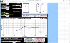
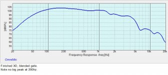
I finally have the crossover for the Visaton HT / Vifa speaker. After listening to it without BSC it sounded thin and horrible so I had to go back and add BSC (Baffle Step Correction) plus a notch filter for the tweeter. Below is the final expected response. Ignore the peak at 200 Hz, it's a measurement anomaly. The crossover has 11 components the largest being a 2mh coil on the woof so even though it uses a lot of parts it will be easy to build and fit in the box.
Nearfield measurements place f3 at about 83Hz in this .23 enclosure so it goes down quite a bit lower than what you're modeling. I'd build a .25 for an expected F3 of about 81hz.
Nearfield measurements place f3 at about 83Hz in this .23 enclosure so it goes down quite a bit lower than what you're modeling. I'd build a .25 for an expected F3 of about 81hz.
Attachments
Last edited:
Cool. Looks nice and flat but why is it at 65 db though? Is your measured frd file not at 1W, or can you normalise it to 1W?
It's not measured at 2.83 at 1 M. That's a simulation from PCD. I haven't measured the speaker yet and when I do I'll have to splice it together. I'll take a gated response down to 200 then take a nearfield below that and splice it together. Actually that crossover is OK but probably excessive for this speaker. It's better to just correct the glaring issues and get on with it. This is nearly as good and it only requires 6 components. It's a toss up whether a $50 worth of drivers is worth $30 in parts to make changes that are, in the end, barely audible.
But will post them if you want.
Attachments
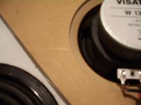
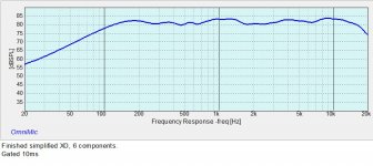
Just got it wired up and starting measurements. First is Gated measured very near 1 meter. Sensitivity will end up being about 82 or 83 db 1w/1m, maybe higher.
Second is nearfield on woofer showing slope. I'll bop into Excel and patch them together later tonight or tomorrow. Actually, after all the hassle I had with this it's a decent little speaker. It could use another ohm or two of padding on the tweeter which I'll do tomorrow but it's a decent deal for $100. As odd as it seems most speakers that measure flat on the tweeter sound hot and/or harsh. This doesn't sound harsh but it does have a slight edge. A little more padding, probably 2 db will fix that. I've listened to it before this version and its OK once it's padded down enough.
Second is nearfield on woofer showing slope. I'll bop into Excel and patch them together later tonight or tomorrow. Actually, after all the hassle I had with this it's a decent little speaker. It could use another ohm or two of padding on the tweeter which I'll do tomorrow but it's a decent deal for $100. As odd as it seems most speakers that measure flat on the tweeter sound hot and/or harsh. This doesn't sound harsh but it does have a slight edge. A little more padding, probably 2 db will fix that. I've listened to it before this version and its OK once it's padded down enough.
Attachments
Last edited:
You might check out the Visaton AL-130 Aluminum cone driver. It probably fits your specifications. It's a tad more expensive but has been successfully used in several projects. Paired with one of the less expensive Vifa tweets if I recall correctly, so there is a crossover designed for it somewhere. Yea, here's a goo link: http://www.diyaudio.com/forums/multi-way/214989-tqwt-visaton-al130-g20sc-finished.html
yes that is the crossover I posted a couple of years ago in the build thread of my main speaker system using the AL130 and G20SC.
I cant really take any credit for it though, as it was a re-hash of the 'Vib130TL crossover on the visaton site. All I did was add a 47uH choke to attenuate the breakup peak better than the original.
Some of the original photos of the build and sim pictures have vanished mysteriously since the gallerys disappearance a while back. Most of the links in my thread arent working in all probablilty.
Heres what IS still here on the site:
The LP C1 was reduced to 5uF in the end, as it stressed the tweeter resonance a little (system7 alerted me to this, I actually didnt realise that I had forgotten to change it earlier!)
When im at home Ill dig out the original pictures and re-post them, should you (or Dr. nick?) be interested.
I also have the .frd and .zma on file, if those are handy to anyone.
Last edited:
Thanks for posting the frd files. I just wonder if you have some resistance in series with the woofer in the PCD crossover model, to drop the sensitivity so much?
No I was measuring them at very low levels. Probably around 1 volt. I don't have a volt meter on the output although I probably should. I don't want to cook my tweets, it takes 7 days to get a replacement and they cost $18 plus shipping.
I have a very high noise floor here, it's about 50db avg all the time. I can set the mic with the SPL meter and measure a nearly constant 45-60 db background rumble. I'd have to really hammer the tweeter to get a clean measurement over that noise. Omnimic uses a CD for it's excitation. Optionally you can use the sound card directly but you can't choose which track you want when you use the sound card. There is a track on the CD with a frequency limited sine sweep 500hz and up I think, that I could use but I'm lazy and didn't use the CD. I really should try it. But it won't make any difference in terms of noise.
I just rented a small space downstairs below me in the laundry room. It's below ground in the concrete foundation so it should be much quieter.
- Status
- This old topic is closed. If you want to reopen this topic, contact a moderator using the "Report Post" button.
- Home
- Loudspeakers
- Multi-Way
- Design for a cheap two way for use as rear speakers in 5.1 setup